
Specifications


CONNECTIONS – PLUMBING
24
PIPE SIZES
The pipe sizing for hot water supply systems should be carried out by persons competent to do so, choosing
the most suitable pipe size to ensure adequate flow for each individual application. Reference to the
technical specifications of the water heater and local regulatory authority requirements must be made.
To achieve true mains pressure operation, the cold water line to the water heater should be the same size or
bigger than the hot water line from the water heater.
The minimum recommended cold pipe size is DN20.
GAS INLET
The gas connection is made at the underside of the water heater. The pipe work must be cleared of foreign
matter before connection and purged before attempting to operate the water heater. An isolation valve and
disconnection union must be installed to allow servicing and removal of the water heater (refer to the
diagram on page 23).
Note: Refer to the Gas Installations Standard AS 5601 or AS/NZS 5601.1 for the correct method of sizing
the gas supply pipe to the water heater. The pipe size selection must take into account the high gas input of
this water heater (refer to table on page 21) as well as all of the other gas appliances in the premises.
Warning: Always isolate the water heater before pressure testing the gas supply system. Disconnect the
water heater after the isolation valve to prevent the risk of serious damage to the gas control. The Rheem
warranty does not cover damage of any nature resulting from failure to observe this precaution. Refer to
rating label for gas types and pressures.
TEMPERATURE PRESSURE RELIEF VALVE
The temperature pressure relief valve is supplied and installed in position at the top of the water heater
cylinder, inside the jacket.
The temperature pressure relief valve can be assessed by removing the plastic cover panel (refer to
“Accessing the Temperature Pressure Relief Valve” on page 11).
A copper drain line must be fitted to the temperature pressure relief valve (refer to "Relief Valve Drain" on
page 25). The drain line connects to the underside of the water heater.
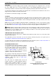
EXPANSION CONTROL VALVE
Local regulations may make it mandatory to install
an expansion control valve (ECV) in the cold water
line to the water heater. In other areas, an ECV is
required if the saturation index is greater than +0.4
(refer to “Water Supplies” on page 12) or in a
corrosive water area where there are sufficient
quantities of silica dissolved in the water.
The expansion control valve must be the last valve
installed prior to the water heater as shown in
diagram. A copper drain line must be fitted to the
expansion control valve (refer to "Relief Valve
Drain" on page 25).
The valve must be insulated with closed cell
polymer insulation or similar (minimum thickness
9 mm) and the insulation installed so as not to
impede the operation of the valve. The insulation
must be weatherproof and UV resistant if exposed.
T&PR
DRAIN
NON-RETURN
VALVE
(Required to be
fitted with ECV)
PRESSURE
LIMITING VALVE
GATE VALVE
OR
BALL VALVE
EXPANSION
CONTROL
VALVE
(Required by some
authorities)
HOT
WATER
GAS
COCK
GAS
COLD WATER
POWER
CORD
Gas Water Heater
Cold and Hot Water and Gas Connection Details
(with Expansion Control Valve)