
Specifications


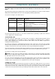


Table Of Contents
- Contents
- About Your Water Heater
- Water Heater Application
- Model Type
- Mains Pressure
- Solar Operation
- How Hot Should The Water Be?
- Hotter Water Increases The Risk Of Scald Injury
- Warning
- Safety
- Precautions
- Pipe Work And Insulation
- Freeze Protection
- Solar Monitor
- Bleeding The Solar Collector(S)
- To Turn Off The Water Heater
- To Turn On The Water Heater
- Going On Holidays
- How Do I Know If The Water Heater Is Installed Correctly?
- Victorian Customers
- Does The Water Chemistry Affect The Water Heater?
- How Long Will The Water Heater Last?
- Regular Care
- Water Supplies
- Save A Service Call
- Not Enough Hot Water (Or No Hot Water)
- Temperature Pressure Relief Valve Running
- Expansion Control Valve Running
- In-Series Water Heater Operating Too Frequently
- Collector Glass
- Noise From The Solar Collectors
- Green LED Is Not Illuminated On Solar Monitor
- Red LED Illuminated on Solar Monitor
- Circulator Operates at Night
- Higher Than Expected Gas Bills
- Installation – System
- Installation – Solar Storage Tank
- Solar Water Heater Storage Tank Location
- Safe Tray
- Mains Water Supply
- Tank Water Supply
- Wall Bracket
- Hot Water Delivery
- Circulated Hot Water Flow And Return System
- Reducing Heat Losses
- Anode
- Saddling - Pipe Work
- Anti-Freeze Heating Unit
- Backing Plate
- Dimensions And Technical Data
- Typical Installation (Remote Boost) – Outdoor Location
- Typical Installation (Remote Boost) – Indoor Location
- Typical Installation (Integrated Boost) – Outdoor Location
- Installation – Solar Control Unit
- Installation – Solar Collector(s)
- Connections – Plumbing
- Connections – Electrical
- Commissioning
- Draining The Solar Collector(s)
- Draining The Water Heater
- Vulcan Solar Water Heater Warranty – Australia Only –
- 1. The Vulcan Warranty – General
- 2. Terms Of The Vulcan Warranty And Exclusions To It
- 3. What Is Covered By The Vulcan Warranty For The Water Heaters Detailed In This Document
- 4. Entitlement To Make A Claim Under This Warranty
- 5. How To Make A Claim Under This Warranty
- 6. The Australian Consumer Law
COMMISSIONING
49
IN-SERIES BOOSTER
Refer to the Owner‟s Guide and Installation Instructions supplied with the in-series water heater for the
commissioning procedure of the in-series water heater.
If a continuous flow gas water heater has been installed as an in-series gas booster to the solar water
heater, then to complete the installation, it is necessary to check the gas supply pressure at the inlet to the
in-series gas booster, and also the minimum test point pressure and the maximum test point pressure of the
in-series gas booster. Refer to “Gas Inlet Pressure” and to “Burner Gas Pressure” in the Owner‟s Guide and
Installation Instructions supplied with the in-series gas booster.
PRESET OUTLET TEMPERATURE
Note: AS 3498 requires that a water heater provides the means to inhibit the growth of Legionella bacteria in
potable water. If this water heater is installed with an in-series continuous flow gas booster, then this
requirement of AS 3498 can be satisfied provided the booster is energised, its preset outlet temperature
setting is 70°C or higher and a remote temperature controller is not used.
If this water heater is installed with an in-series storage booster, then this requirement of AS 3498 can be
satisfied provided the storage booster is energised and its thermostat setting is 60°C or higher.
It will be necessary to check and if required to adjust the preset outlet temperature setting of the continuous
flow water heater or the thermostat setting of a storage water heater when it is installed as an in-series
booster to a solar water heater or if it is an existing water heater and a solar water heater is then installed.
Refer to the Owner‟s Guide and Installation Instructions supplied with the in-series continuous flow gas
booster for the procedure to check and adjust the preset outlet temperature if required.
Refer to the Owner‟s Guide and Installation Instructions supplied with the in-series storage booster for the
procedure to check and adjust the thermostat setting if required.
Note: Consideration must be given to the delivery temperature to any ablution and public areas such as a
bathroom, ensuite or public amenities. Refer to “Hot Water Delivery” on page 26 and to the schematics of
“Two Temperature Zones Using A Temperature Limiting Device” on page 27.
BLEEDING THE SOLAR COLLECTOR(S)
Upon completion of the installation, it is necessary to purge
the air from the collector circuit.
To purge air from the collector circuit:
Ensure the water heater is full of water and all of the hot
taps are turned off.
Using a flat blade screwdriver, open the bleed valve
fitted adjacent to the solar hot water inlet of the solar
storage tank (see diagram).
The mains pressure will force water to flow from the tank
and through the pipe work, forcing air from the collector
circuit through the bleed valve. This is evidenced by
spurting of water from the drain line connected to the
bleed valve.
Warning: Stand well aside of the air bleed valve
drain pipe discharge point and exercise care to avoid any
splashing of water, as water or in some circumstances
steam discharged from the solar collector(s) may be of a
very high temperature.
Close the bleed valve when water runs freely from the
drain line.
AIR BLEED VALVE & SOLAR
NON RETURN VALVE ASSEMBLY
Solar Pumped Open Circuit