
Specifications


Table Of Contents
- Contents
- About Your Water Heater
- Water Heater Application
- Model Type
- Mains Pressure
- Solar Operation
- How Hot Should The Water Be?
- Hotter Water Increases The Risk Of Scald Injury
- Warning
- Safety
- Precautions
- Pipe Work And Insulation
- Freeze Protection
- Solar Monitor
- Bleeding The Solar Collector(S)
- To Turn Off The Water Heater
- To Turn On The Water Heater
- Going On Holidays
- How Do I Know If The Water Heater Is Installed Correctly?
- Victorian Customers
- Does The Water Chemistry Affect The Water Heater?
- How Long Will The Water Heater Last?
- Regular Care
- Water Supplies
- Save A Service Call
- Not Enough Hot Water (Or No Hot Water)
- Temperature Pressure Relief Valve Running
- Expansion Control Valve Running
- In-Series Water Heater Operating Too Frequently
- Collector Glass
- Noise From The Solar Collectors
- Green LED Is Not Illuminated On Solar Monitor
- Red LED Illuminated on Solar Monitor
- Circulator Operates at Night
- Higher Than Expected Gas Bills
- Installation – System
- Installation – Solar Storage Tank
- Solar Water Heater Storage Tank Location
- Safe Tray
- Mains Water Supply
- Tank Water Supply
- Wall Bracket
- Hot Water Delivery
- Circulated Hot Water Flow And Return System
- Reducing Heat Losses
- Anode
- Saddling - Pipe Work
- Anti-Freeze Heating Unit
- Backing Plate
- Dimensions And Technical Data
- Typical Installation (Remote Boost) – Outdoor Location
- Typical Installation (Remote Boost) – Indoor Location
- Typical Installation (Integrated Boost) – Outdoor Location
- Installation – Solar Control Unit
- Installation – Solar Collector(s)
- Connections – Plumbing
- Connections – Electrical
- Commissioning
- Draining The Solar Collector(s)
- Draining The Water Heater
- Vulcan Solar Water Heater Warranty – Australia Only –
- 1. The Vulcan Warranty – General
- 2. Terms Of The Vulcan Warranty And Exclusions To It
- 3. What Is Covered By The Vulcan Warranty For The Water Heaters Detailed In This Document
- 4. Entitlement To Make A Claim Under This Warranty
- 5. How To Make A Claim Under This Warranty
- 6. The Australian Consumer Law
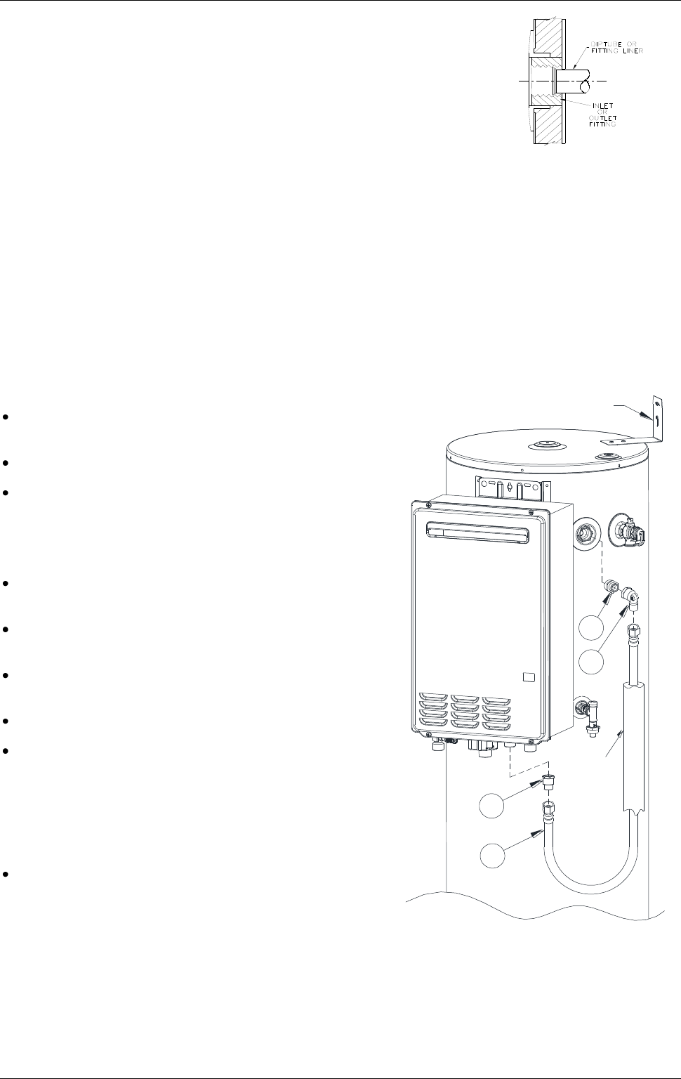
CONNECTIONS – PLUMBING
43
A disconnection union must always be provided at the cold water inlet,
solar cold water outlet, solar hot water inlet and hot water outlet on the
water heater to allow for disconnection of the water heater.
This water heater has either a plastic dip tube or fitting liner in the inlet and
outlet fittings (see diagram). These must be in place for the water heater to
function properly. Do not remove or damage them by using heat nearby.
They will be pushed into the correct position as the fitting is screwed in.
IN-SERIES BOOSTER – INTEGRATED
A braided hose, 750 mm long 12 mm diameter, is supplied for connecting between the solar storage tank
and a Rheem 871 series 24 litre or a 874 series 18 litre model in-series gas booster mounted onto the
storage tank.
It is recommended to install the fittings associated with the solar control unit prior to mounting the in-series
gas booster. Refer to “Installation – Solar Control Unit” on page 34. The air bleed and solar non return valve
assembly must be fitted prior to mounting the in-series gas booster. Refer to steps 12 and 13 on page 36.
Fit the wall bracket and secure the solar storage tank to the wall prior to the mounting of an in-series gas
booster to the solar storage tank. Refer to “Wall Bracket” on page 26. To integrate the in-series gas booster
onto the solar storage tank, refer to “Backing Plate” on page 30.
Notes
Numbers in parentheses refer to items on diagram on
page 43.
The braided hose has compression fitting connections.
Use thread sealing tape or an approved thread sealant
on all fittings.
To connect the braided hose to the solar storage tank and
in-series gas booster:
Fit the ¾” x ½” hex nipple (1) to the hot water outlet of
the solar storage tank.
Fit the ½” x ½”elbow (2) to the hex nipple (1),
orientating the elbow downwards.
Fit the ¾” x ½” reducing adaptor (3) to the water inlet of
the in-series gas booster.
The spare ½” x ½” adaptor fitting can be discarded.
Insulate the full length of the braided hose (4) with a
closed cell type insulation or equivalent (installer to
supply).
The insulation shall be at least 13 mm thick, however
thicker insulation may be required to comply with the
requirements of AS/NZS 3500.4.
Connect one end of the braided hose (4) to the
elbow (2) at the hot water outlet of the solar storage
tank and the other end to the adaptor (3) at the water
inlet to the in-series gas booster.
SUPPLIED WITH VS160 SOLAR STORAGE TANK
1. Hex nipple ¾” x ½”
2. Elbow ½” x ½”
3. Adaptor – ¾” x ½” or ½” x ½”
4. Braided hose
SUPPLIED WITH VS160 SOLAR STORAGE TANK
1. Nipple BSP ¾" x ½" 3. Adapter ¾" F x ½" M OR ½" F x ½" M
VS160 Tank to Booster Connection
Installation (Exploded View)
SK6260 09/12 REV CD (A4)
2
3
2. Elbow ½" F x ½" M 4. Braided hose 750 Long x 12 Dia.
4
1
HOSE TO BE
FULLY
INSULATED
BY
INSTALLER
WALL
BRACKET