
Specifications
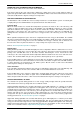


Table Of Contents
- Contents
- About Your Water Heater
- Water Heater Application
- Model Type
- Mains Pressure
- Solar Operation
- How Hot Should The Water Be?
- Hotter Water Increases The Risk Of Scald Injury
- Warning
- Safety
- Precautions
- Pipe Work And Insulation
- Freeze Protection
- Solar Monitor
- Bleeding The Solar Collector(S)
- To Turn Off The Water Heater
- To Turn On The Water Heater
- Going On Holidays
- How Do I Know If The Water Heater Is Installed Correctly?
- Victorian Customers
- Does The Water Chemistry Affect The Water Heater?
- How Long Will The Water Heater Last?
- Regular Care
- Water Supplies
- Save A Service Call
- Not Enough Hot Water (Or No Hot Water)
- Temperature Pressure Relief Valve Running
- Expansion Control Valve Running
- In-Series Water Heater Operating Too Frequently
- Collector Glass
- Noise From The Solar Collectors
- Green LED Is Not Illuminated On Solar Monitor
- Red LED Illuminated on Solar Monitor
- Circulator Operates at Night
- Higher Than Expected Gas Bills
- Installation – System
- Installation – Solar Storage Tank
- Solar Water Heater Storage Tank Location
- Safe Tray
- Mains Water Supply
- Tank Water Supply
- Wall Bracket
- Hot Water Delivery
- Circulated Hot Water Flow And Return System
- Reducing Heat Losses
- Anode
- Saddling - Pipe Work
- Anti-Freeze Heating Unit
- Backing Plate
- Dimensions And Technical Data
- Typical Installation (Remote Boost) – Outdoor Location
- Typical Installation (Remote Boost) – Indoor Location
- Typical Installation (Integrated Boost) – Outdoor Location
- Installation – Solar Control Unit
- Installation – Solar Collector(s)
- Connections – Plumbing
- Connections – Electrical
- Commissioning
- Draining The Solar Collector(s)
- Draining The Water Heater
- Vulcan Solar Water Heater Warranty – Australia Only –
- 1. The Vulcan Warranty – General
- 2. Terms Of The Vulcan Warranty And Exclusions To It
- 3. What Is Covered By The Vulcan Warranty For The Water Heaters Detailed In This Document
- 4. Entitlement To Make A Claim Under This Warranty
- 5. How To Make A Claim Under This Warranty
- 6. The Australian Consumer Law
INSTALLATION – SOLAR STORAGE TANK
30
ANTI-FREEZE HEATING UNIT
Additional freeze protection is provided by the anti-freeze heating unit. The anti-freeze heating unit is for
heating the water at the bottom of the solar storage tank at times of very low cold water temperature. The
anti-freeze heating unit provides additional energy to the water to assist in the prevention of freezing in the
solar pipe work and solar collector(s). The anti-freeze heating unit is controlled by the solar controller and will
only be energised when the water temperature is very low and the circulator activates in the frost mode. The
water temperature is monitored by the cold sensor.
If the water temperature at the bottom of the solar storage tank is very low when the circulator activates in
Freeze Protection operation mode, the anti-freeze heating unit will be energised and will heat the water by a
few degrees. The anti-freeze heating unit will be de-energised when either the frost mode is shut down or the
water temperature has risen by a few degrees.
The anti-freeze heating unit is supplied with power from the solar control unit. The power outlet to the solar
control unit must be switched on for the anti-freeze heating unit to operate and offer additional freeze
protection.
BACKING PLATE
The backing plate has been provided to support an in-series gas booster. Fit the wall bracket and secure the
solar storage tank to the wall prior to the mounting of an in-series gas booster to the solar storage tank.
Refer to “Wall Bracket” on page 26.
It is recommended to install the fittings associated with the solar control unit prior to mounting the in-series
gas booster. Refer to “Installation – Solar Control Unit” on page 34. The air bleed and solar non return valve
assembly must be fitted prior to mounting the in-series gas booster. Refer to steps 12 and 13 on page 36.
To mount the 871 series gas booster:
Remove the two mounting bolts from the centre top and
centre bottom of the backing plate.
Locate the in-series gas booster and line up the mounting
holes at the top and bottom of the in-series gas booster with
the holes on the backing plate.
Fix the in-series gas booster to the backing plate using the
two mounting bolts provided.
Note: The two screws provided in the ground kit (299158)
can be discarded.
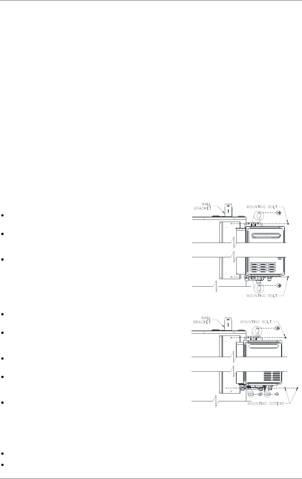
To mount the 874 series gas booster:
Remove the mounting bolt from the centre top of the backing
plate.
Locate the in-series gas booster and line up the mounting
hole at the top of the in-series gas booster with the hole on
the backing plate.
Fix the top bracket of the in-series gas booster to the backing
plate using the mounting bolt provided.
Locate the two holes in the bottom bracket of the in-series
gas booster over the two holes toward the bottom of the
bracket.
Fix the bottom bracket of the in-series gas booster to the
backing plate using the two screws provided in the ground kit
(299158).
If an in-series gas booster is not to be mounted on the backing plate, the backing plate can be removed from
the solar storage tank. To remove the backing plate:
Remove the four mounting screws and two mounting bolts and remove the mounting plate.
Refit the four mounting screws and two mounting bolts to the holes in the solar storage tank jacket.
871 series gas booster mounting
874 series gas booster mounting