
Specifications
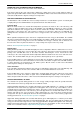


Table Of Contents
- Contents
- About Your Water Heater
- Water Heater Application
- Model Type
- Mains Pressure
- Solar Operation
- How Hot Should The Water Be?
- Hotter Water Increases The Risk Of Scald Injury
- Warning
- Safety
- Precautions
- Pipe Work And Insulation
- Freeze Protection
- Solar Monitor
- Bleeding The Solar Collector(S)
- To Turn Off The Water Heater
- To Turn On The Water Heater
- Going On Holidays
- How Do I Know If The Water Heater Is Installed Correctly?
- Victorian Customers
- Does The Water Chemistry Affect The Water Heater?
- How Long Will The Water Heater Last?
- Regular Care
- Water Supplies
- Save A Service Call
- Not Enough Hot Water (Or No Hot Water)
- Temperature Pressure Relief Valve Running
- Expansion Control Valve Running
- In-Series Water Heater Operating Too Frequently
- Collector Glass
- Noise From The Solar Collectors
- Green LED Is Not Illuminated On Solar Monitor
- Red LED Illuminated on Solar Monitor
- Circulator Operates at Night
- Higher Than Expected Gas Bills
- Installation – System
- Installation – Solar Storage Tank
- Solar Water Heater Storage Tank Location
- Safe Tray
- Mains Water Supply
- Tank Water Supply
- Wall Bracket
- Hot Water Delivery
- Circulated Hot Water Flow And Return System
- Reducing Heat Losses
- Anode
- Saddling - Pipe Work
- Anti-Freeze Heating Unit
- Backing Plate
- Dimensions And Technical Data
- Typical Installation (Remote Boost) – Outdoor Location
- Typical Installation (Remote Boost) – Indoor Location
- Typical Installation (Integrated Boost) – Outdoor Location
- Installation – Solar Control Unit
- Installation – Solar Collector(s)
- Connections – Plumbing
- Connections – Electrical
- Commissioning
- Draining The Solar Collector(s)
- Draining The Water Heater
- Vulcan Solar Water Heater Warranty – Australia Only –
- 1. The Vulcan Warranty – General
- 2. Terms Of The Vulcan Warranty And Exclusions To It
- 3. What Is Covered By The Vulcan Warranty For The Water Heaters Detailed In This Document
- 4. Entitlement To Make A Claim Under This Warranty
- 5. How To Make A Claim Under This Warranty
- 6. The Australian Consumer Law
INSTALLATION – SOLAR STORAGE TANK
26
TANK WATER SUPPLY
If the water heater is supplied with water from a tank supply and a minimum water supply pressure of
200 kPa at the water heater cannot be achieved, then a pressure pump system must be installed to allow the
solar circuit system to operate. Care must be taken to avoid air locks. The cold water line from the supply
tank should be adequately sized and fitted with a full flow gate valve or ball valve. Consideration must be
given to any minimum water supply pressure requirements of an in-series water heater.
WALL BRACKET
It is a requirement to secure the solar storage tank to the wall.
Fit the wall bracket and secure the solar storage tank to the wall
prior to the mounting of an in-series gas booster to the solar
storage tank.
The top of the unit is to be secured to the wall with the wall
bracket, wall plugs and screws provided. If the wall plugs and
screws provided are not suitable for the wall construction, then
other suitable anchors are to be used.
To fit the wall bracket:
Position the bracket against the wall, ensuring the bracket
is centered at the rear of the storage tank top, and mark the
fixing points on the wall where the bracket is to be secured.
Drill holes in the wall to receive the wall plugs supplied or
other suitable anchors for the wall bracket.
Fix the wall bracket to the wall using the screws provided or
other suitable anchors.
Secure the bracket to the top of the water heater using the self tapping screws provided.
HOT WATER DELIVERY
This water heater can deliver water at temperatures which can cause scalding.
It is necessary and we recommend that a temperature limiting device be fitted between the water heater and
the hot water outlets in any ablution and public areas such as a bathroom, ensuite or public amenities, to
reduce the risk of scalding. The installing plumber may have a legal obligation to ensure the installation of
this water heater meets the delivery water temperature requirements of AS/NZS 3500.4 so that scalding
water temperatures are not delivered to a bathroom, ensuite or other ablution or public area.
The temperature limiting device should have a specified:
„minimum temperature differential‟ between the hot water inlet and the tempered water outlet of no
greater than 10°C, when used with a solar water heater and continuous flow water heater
„maximum permitted pressure variation‟ in either supply between the hot water inlet and the cold water
inlet of no less than 15% when used with a continuous flow water heater.
Refer to the specifications of the temperature limiting device.
Warning: Temperature controllers must not be fitted to the in-series water heater as part of a solar water
heater system because water at a temperature much higher than the controller setting can be delivered.
Where a temperature limiting device is installed adjacent to the in-series water heater, the cold water line to
the temperature limiting device can be branched off the cold water line either before or after the isolation
valve and pressure limiting valve to the solar storage tank, but it MUST BE before the non return valve. If an
expansion control valve is required, it must always be installed after the non return valve and be the last
valve prior to the solar storage tank.
Warning: A non return valve MUST BE installed on the cold water line to the solar storage tank AFTER
the cold water branch to a temperature limiting device. Due to the higher water temperatures generated
under certain conditions in the solar collector(s) of this solar water heater, an additional effective back-flow
prevention device also should be used as an extra safeguard. Valve manufacturer RMC recommends Dual
Check Valve model N7150, as being suitable for this application.