
Specifications
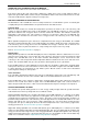


Table Of Contents
- Contents
- About Your Water Heater
- Water Heater Application
- Model Type
- Mains Pressure
- Solar Operation
- How Hot Should The Water Be?
- Hotter Water Increases The Risk Of Scald Injury
- Warning
- Safety
- Precautions
- Pipe Work And Insulation
- Freeze Protection
- Solar Monitor
- Bleeding The Solar Collector(S)
- To Turn Off The Water Heater
- To Turn On The Water Heater
- Going On Holidays
- How Do I Know If The Water Heater Is Installed Correctly?
- Victorian Customers
- Does The Water Chemistry Affect The Water Heater?
- How Long Will The Water Heater Last?
- Regular Care
- Water Supplies
- Save A Service Call
- Not Enough Hot Water (Or No Hot Water)
- Temperature Pressure Relief Valve Running
- Expansion Control Valve Running
- In-Series Water Heater Operating Too Frequently
- Collector Glass
- Noise From The Solar Collectors
- Green LED Is Not Illuminated On Solar Monitor
- Red LED Illuminated on Solar Monitor
- Circulator Operates at Night
- Higher Than Expected Gas Bills
- Installation – System
- Installation – Solar Storage Tank
- Solar Water Heater Storage Tank Location
- Safe Tray
- Mains Water Supply
- Tank Water Supply
- Wall Bracket
- Hot Water Delivery
- Circulated Hot Water Flow And Return System
- Reducing Heat Losses
- Anode
- Saddling - Pipe Work
- Anti-Freeze Heating Unit
- Backing Plate
- Dimensions And Technical Data
- Typical Installation (Remote Boost) – Outdoor Location
- Typical Installation (Remote Boost) – Indoor Location
- Typical Installation (Integrated Boost) – Outdoor Location
- Installation – Solar Control Unit
- Installation – Solar Collector(s)
- Connections – Plumbing
- Connections – Electrical
- Commissioning
- Draining The Solar Collector(s)
- Draining The Water Heater
- Vulcan Solar Water Heater Warranty – Australia Only –
- 1. The Vulcan Warranty – General
- 2. Terms Of The Vulcan Warranty And Exclusions To It
- 3. What Is Covered By The Vulcan Warranty For The Water Heaters Detailed In This Document
- 4. Entitlement To Make A Claim Under This Warranty
- 5. How To Make A Claim Under This Warranty
- 6. The Australian Consumer Law
25
INSTALLATION – SOLAR STORAGE TANK
SOLAR WATER HEATER STORAGE TANK LOCATION
The solar storage tank is suitable for either outdoor or indoor installation. If an in-series gas booster is
mounted to the solar storage tank, then the installation must be outdoors. Whether located outdoor or indoor,
the solar storage tank should be installed close to the most frequently used outlet and its position chosen
with safety and service in mind.
Consideration must also be given to the position of the solar storage
tank in relation to the solar collector(s). There are limitations on the
maximum length of the solar hot and solar cold pipes between the
solar storage tank and the solar collector(s). Refer to “Solar
Collector Location” on page 37 and to “Pipe Lengths” on page 39.
Clearance must be allowed for servicing of the solar storage tank.
The solar storage tank must be accessible without the use of a
ladder or scaffold. Make sure the temperature pressure relief valve
lever is accessible and the front cover, thermostat and booster
heating unit can be removed for service.
You must be able to read the information on the rating plate. If
possible leave headroom of one water heater height so the anode
can be inspected or replaced. Remember you may have to remove
the entire solar storage tank later for servicing.
It is recommended the solar storage tank be installed at ground or
floor level and must stand vertically upright. The base of the water
heater is made of corrosion resistant material, and it may be placed
directly in contact with the supporting surface. It is not necessary to
allow for free air circulation under the base of the water heater.
Note: The water heater should not be placed in direct contact with a
concrete surface that is less than two months old and not fully cured
as this may attack the metal coating of the water heater base. A
moisture barrier should be used between the two surfaces in this
instance.
Remember all local authorities have regulations about putting water heaters into roof spaces.
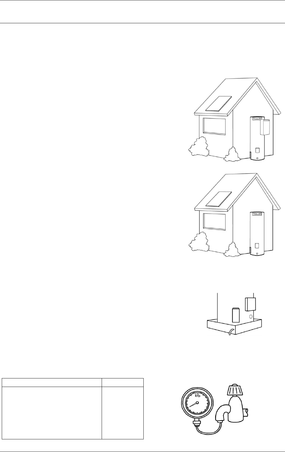
SAFE TRAY
Where damage to property can occur in the event of the water
heater leaking, the water heater must be installed in a safe tray.
Construction, installation and draining of a safe tray must comply
with AS/NZS 3500.4 and all local codes and regulatory authority
requirements. AS/NZS 3500.4 also has particular requirements
when a safe tray must be installed.
MAINS WATER SUPPLY
Where the mains water supply pressure exceeds that shown in the table below, an approved pressure
limiting valve is required and should be fitted as shown in the installation diagram (refer to diagram on
page 42).
Model
160
Relief valve setting
1000 kPa
Expansion control valve setting *
850 kPa
Max. mains supply pressure
With expansion control valve
680 kPa
Without expansion control valve
800 kPa
Min. mains supply pressure
200 kPa
* Expansion control valve not supplied with the water heater.