
Instructions / Assembly


2
metal surfaces on which the old gasket was attached on the
transition pan and the lower air box.
The outside edge may be scraped with a putty knife, sanded
lightly with sand paper, and washed with a light soap and
water mixture to remove the old gasket material and adhe-
sive.
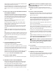
15. INSTALLING THE NEW PILOT BURNER AND PIEZO
ELECTRODE ASSEMBLY:
Install the new pilot burner and piezo electrode assembly by
threading the connection ends of the assembly thru the hole in
the mounting plate from the backside and pushing the small
side of the orange grommet into the hole of the mounting
plate. Refer to Figure 4.
Take care not to damage the grommet as you push it
through the hole to the front.
Ensure the grommet is fully seated. The smaller rubber
flange should be completely through to the front of the
mounting plate to seat correctly.
Attach the new pilot burner and piezo electrode assembly
to the pilot mounting bracket with the screws removed
earlier.
NOTE: The old pilot may feature a loop around the burner
chamber. This feature is not required for the new pilot assem-
bly.
Make sure the screws pull the assembly up tight against the
mounting bracket on the burner plate to ensure proper posi-
tioning of the new pilot burner and peizo electrode assem-
bly.
16. INSPECT THERMOCOUPLE:
Make sure that a minimum of peizo wire & copper thermocou-
ple wire is exposed at the grommet.
17. INSTALL BURNER/PILOT ASSEMBLY:
Install the burner/pilot assembly.
(2 torx head screws required in upper position.)
Make sure the speed clips are tight in place upon reinstalla-
tion of the burner/pilot assembly and the inner door. Extra
speed clips are provided in the event some are lost or dam-
aged in the removal of these parts.
Tighten the T20 Torx head screws to no more than 15 inch
pounds of torque using the TORX head tool, DO NOT
over tighten. DO NOT USE POWER TOOLS.
18. INSTALL LOWER AIR BOX:
Install the lower air box. (2 - #8 x 32 Sems Screws Required).
19. PREPARE TO INSTALL THE INNER DOOR:
Remove the old door gasket and clean the metal surfaces
on which the old gasket was attached on the back of the
door and the front of the burner/pilot assembly.
The outside edge may be scraped with a putty knife, sanded
lightly with sand paper, and washed with a light soap and
water mixture to remove the old gasket material and adhe-
sive.
!
WARNING:
DO NOT use flammable liquids such as
gasoline, paint thinners, or solvents to remove the old gas-
ket material and adhesive.
19A. Install a new gasket on the back of the inner door by
aligning the holes in the gasket with the holes on the inner
door.
20. INSTALL THE INNER DOOR:
Mount the inner door assembly to the burner assembly and
reassemble in the reverse order of removal. Make sure the
gasket is fully seated.
When connecting the pilot supply tube, make sure it is seated into
the valve straight to help prevent crossthreading of the connection
and an improper alignment with the gas valve. Use a wrench to
snug the connection to the valve to prevent gas leakage.
When connecting the burner supply tube, make sure the con-
nection is not cross threaded.
When connecting the thermocouple, make sure it is insert-
ed into the valve straight to prevent damage to the ther-
mocouple. The thermocouple should be no more than one
quarter (1/4) turn beyond hand tight.
Locate the wire coming from the piezo ignitor and the wire out
of the burner access door. Push the wire connectors together
and slide the protective wire insulator “boot” over the connec-
tion.
Tighten the tamper resistant screws to no more than 15 inch
pounds of torque using the TORX head tool, DO NOT over
tighten. DO NOT USE POWER TOOLS.
!
WARNING: Failure to properly install the burn-
er access door could result in a potentially hazard-
ous situation that could result in death or serious
injury and/or property damage.
21. GAS SUPPLY:
Turn the gas supply on at the main gas line. Refer to the
label on the front of the unit for "Lighting Instructions", or
the Use & Care Manual.
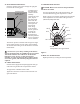
22.. THERMOCOUPLE OPERATION
Check that the pilot is lit and the thermocouple is enveloped
3/8” to 1/2” by the pilot flame by looking through the sight
glass located on the mounting plate.
Turn the gas cock knob to the “ON” position.