
Instructions / Assembly

Attach the new pilot burner and piezo electrode assembly to the
burner plate with the screw removed earlier.
Make sure the screw pulls the assembly up tight against the
bracket on the burner plate to ensure proper positioning of the
new pilot burner and peizo electrode assembly.
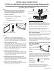
10. INSPECT THERMOCOUPLE:
DO NOT bend the thermocouple within 1”
of tip when installing, as this may damage
the thermocouple. See Figure 5.
Make sure there are no sharp bends
in the thermocouple and that there
is at least a 1” section of straight
thermocouple coming from the
bracket.
Direct all connections to the burner
assembly away from and below the flame
of the burner.
11. PREPARE TO INSTALL THE BURNER ACCESS DOOR:
Remove the old door gasket and clean the metal surfaces on
which the old gasket was attached on the back of the door and
the front of the burner chamber area.
The outside edge may be scraped with a putty knife,
sanded lightly with sand paper, and washed with a light soap
and water mixture to remove the old gasket material and
adhesive.
!
WARNING:
Do not use flammable liquids such as gaso-
line, paint thinners, or solvents to remove the old gasket
material and adhesive.
NOTICE: A new gasket must replace the existing one prior to
reassembly.
Install a new gasket on the back of the Burner Access Door
by removing the pull away tabs on the gasket and sticking the
new gasket to the back of the Burner Access Door, aligning the
holes in the gasket with the holes on the Burner Access Door
for the T20 Torx head screws.
12. INSTALL THE BURNER ACCESS DOOR:
Insert the burner access door assembly back into the burner
chamber and reassemble in the reverse order of removal. Make
sure the gasket is fully seated.
Make sure the speed clips are tight in place upon reinstallation of
the door. Extra speed clips are provided in the event some are lost
or damaged in the removal of the burner access door.
When connecting the pilot supply tube, make sure it is seated into the
valve straight to help prevent crossthreading of the connection and
an improper alignment with the gas valve. Use a wrench to snug the
connection to the valve to prevent gas leakage. Make sure there are
no sharp bends in the pilot supply tube and that there is at least a 1”
section of straight pilot supply tube coming from the bracket.
When connecting the burner supply tube, make sure the connection
is not cross threaded.
When connecting the thermocouple, make sure it is inserted
into the valve straight to prevent damage to the thermocouple.
The thermocouple should be no more than one quarter (1/4)
turn beyond hand tight.
When connecting the piezo ignitor wire to the bottom of the
piezo ignitor striker, make sure to pull all excess wire to the
outside of the burner chamber to prevent unnecessary exposure
to burner flame.
Tighten the T20 torx head screws to no more than 15 inch pounds
of torque using the TORX head tool, DO NOT over tighten.
DO NOT USE POWER TOOLS.
!
WARNING: Failure to properly install the burner access
door could result in a potentially hazardous situation that
could result in death or serious injury and/or property
damage.
13. GAS SUPPLY:
Turn the gas supply on at the main gas line, turn the gas cock
knob “counterclockwise” to the pilot position and relight the
pilot per the lighting instructions located on the heater and in
the Use & Care Manual.
14. THERMOCOUPLE OPERATION
Check that the pilot is lit and the thermocouple is enveloped
3/8” to 1/2” by the pilot flame by looking through the sight glass
located on the door.
Turn the gas cock knob to the “ON” position.
15. MAIN BURNER OPERATION:
Check the operation of the burner through the sight glass
located on the burner access door.
16. CHECK FOR LEAKS:
Check the burner supply tube and pilot supply tube at the gas
control valve for gas leaks with a soap and water solution.
The appearance of bubbles indicate a leak.
Tighten all connections if a leak is found and check once again
with solution.
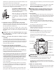
17. TEMPERATURE SETTING:
!
DANGER: Hotter water increases the potential for Hot
Water SCALDS.
Turn the temperature dial to the desired setting. The
recommended starting point temperature is 120°F.
The illustration at the left details the approximate water
temperature for each mark on the Gas Control (Thermostat)
temperature Dial.
18. REPLACE JACKET DOOR:
Replace the jacket door by inserting one end of the door behind
the jacket edge then insert the opposite end of the door behind
the jacket edge and release the door.
2
WARNING
READ ALL INSTRUCTIONS
BEFORE LIGHTING
C
A
U
T
I
O
N
T
H
E
R
I
S
K
O
F
S
C
A
L
D
I
N
J
U
R
Y
W
A
T
E
R
I
N
C
R
E
A
S
E
S
H
O
T
T
E
R
120°F. (Approx.)
110°F. (Approx.)
100°F. (Approx.)
90°F. (Approx.)
80°F. (Approx.)
70°F. (Approx.)
60°F. (Approx.)
130°F. (Approx.)
140°F. (Approx.)
150°F. (Approx.)
160°F. (Approx.)
1” Min.
Figure 5