
Quadra User's Guide
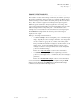
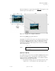

Table Of Contents
- Table of Contents
- Introduction
- Installation and Setup
- Operations
- In This Chapter
- Introduction to Operations
- Setting Output Format
- Testing Outputs
- Selecting an Input Source
- Enabling and Disabling Outputs
- Understanding Auto Sync
- Cropping an Image
- Zooming an Image
- Panning an Image
- Sizing the Output Image
- Using Position
- Adjusting Brightness and Contrast
- Adjusting Hue and Saturation
- Adjusting Sharpness
- Creating a Background
- Creating a 2x2 Monitor Wall
- Command Line Interface
- Image Concepts
- Communications Setup
- Connector Types
- Firmware Upgrades and Troubleshooting
- Technical Specifications
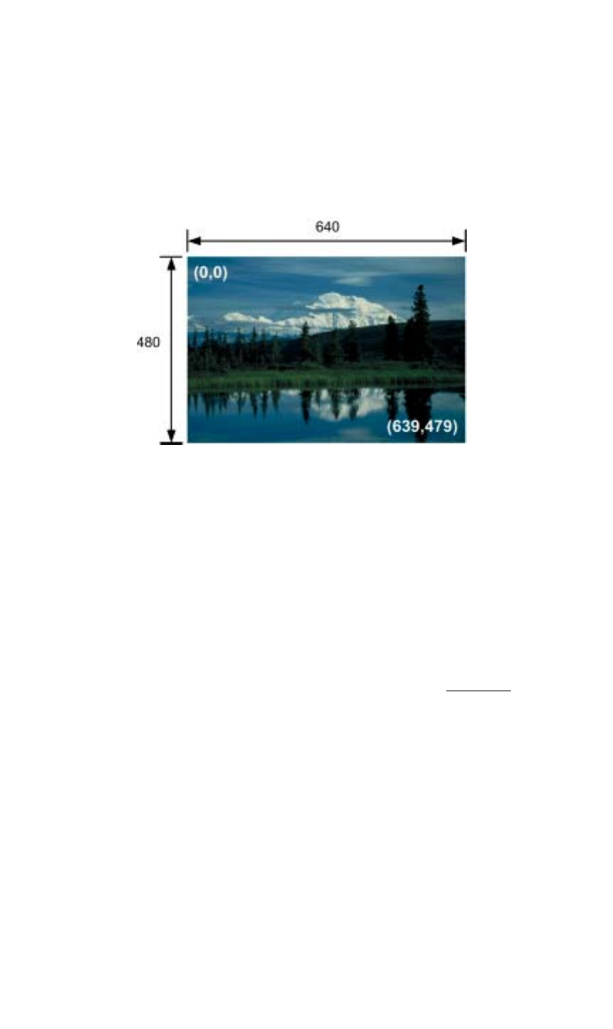
IMAGE CONCEPTS
Image Rectangles
350-7951 Quadra User’s Guide 84
. . . . .
SOURCE
. . . . . . . . .
RECTANGLE
The source rectangle for each input is defined in terms of the input image’s
pixel position in coordinate space. The image’s top left corner is positioned
using these coordinates, and the image’s width and height are defined in the
same way.
In the first example below, the full size source image is 640 pixels wide by 480
lines high.
Figure A-1.
Full Size Source Image
By convention, the upper left corner starts at pixel coordinate (0,0). The
bottom right corner ends at coordinate (639,479). When using Quadra, the
Window Source Rectangle (WSR) command uses the following convention to
define an input’s source rectangle:
x, y, width, height
The x and y parameters define the coordinates of the first pixel located at the
top left of the image. The width and height parameters then define the size of
the image. When using the command line interface, this WSR convention sets
the source rectangle for the selected input.
Thus, to define (and use) the full size picture from Figure A-1 as the output, the
WSR would be defined as:
0 0 640 480