
Quadra User's Guide
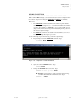
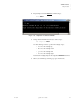
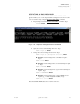
Table Of Contents
- Table of Contents
- Introduction
- Installation and Setup
- Operations
- In This Chapter
- Introduction to Operations
- Setting Output Format
- Testing Outputs
- Selecting an Input Source
- Enabling and Disabling Outputs
- Understanding Auto Sync
- Cropping an Image
- Zooming an Image
- Panning an Image
- Sizing the Output Image
- Using Position
- Adjusting Brightness and Contrast
- Adjusting Hue and Saturation
- Adjusting Sharpness
- Creating a Background
- Creating a 2x2 Monitor Wall
- Command Line Interface
- Image Concepts
- Communications Setup
- Connector Types
- Firmware Upgrades and Troubleshooting
- Technical Specifications
OPERATIONS
Creating a 2x2 Monitor Wall
350-7951 Quadra User’s Guide 50
. . . . .
. . . . . . . . . . . . . . . . . . . . . . . . . . . . .
CREATING A 2X2 MONITOR WALL
Using the WALL command, you can quickly crop all four inputs, configuring
each input’s WSR to exactly 1/4 of the screen. With your output channels
properly connected to a 2x2 monitor wall display, you’re ready to go with one
easy command.
Use the following steps to create a 2x2 monitor wall.
1. Externally to Quadra, split your input source into four identical signals
using a customer-supplied splitter or a DA (Distribution Amplifier).
Refer to Figure 3-2
for reference.
2. Connect each identical source to Quadra’s four input channels.
3. Ensure that each input’s timing is properly (and identically) set. Refer
to the “Loading Input Timing Values
” for instructions.
4. Ensure that each output’s timing is properly (and identically) set Refer
to the “Setting Output Format
” for instructions.
5. Connect Quadra’s outputs to your monitor wall as follows:
~ Connect output #1 to the top left monitor.
~ Connect output #2 to the top right monitor.
~ Connect output #3 to the bottom left monitor.
~ Connect output #4 to the bottom right monitor.
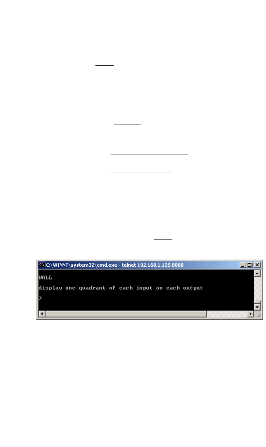
6. Request help text for the WA LL
command. Type:
H WALL Enter
Figure 3-23.
Help Text — Wall Command
7. Issue the Wall command. Type:
WALL Enter
When the command has been executed, each quadrant is properly
cropped and positioned as follows:
~ Input #1 is cropped to the exact upper left quadrant of the
source image.
~ Input #2 is cropped to the exact upper right quadrant of the
source image.