
Quadra User's Guide
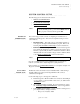
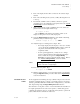
Table Of Contents
- Table of Contents
- Introduction
- Installation and Setup
- Operations
- In This Chapter
- Introduction to Operations
- Setting Output Format
- Testing Outputs
- Selecting an Input Source
- Enabling and Disabling Outputs
- Understanding Auto Sync
- Cropping an Image
- Zooming an Image
- Panning an Image
- Sizing the Output Image
- Using Position
- Adjusting Brightness and Contrast
- Adjusting Hue and Saturation
- Adjusting Sharpness
- Creating a Background
- Creating a 2x2 Monitor Wall
- Command Line Interface
- Image Concepts
- Communications Setup
- Connector Types
- Firmware Upgrades and Troubleshooting
- Technical Specifications

INSTALLATION AND SETUP
Rear Panel
350-7951 Quadra User’s Guide 13
. . . . .
can connect this output to a DVI-capable monitor or an analog RGB
monitor.
7) Graphic Output 2
One DVI-I multi-pin connector is provided for Graphic Output 2,
which is identical to Graphic Output 1.
8) Graphic Output 3
One DVI-I multi-pin connector is provided for Graphic Output 3,
which is identical to Graphic Output 1.
9) Graphic Output 4
One DVI-I multi-pin connector is provided for Graphic Output 4,
which is identical to Graphic Output 1.
10) RS-232 Serial Port
One 9-pin female D-Sub connector is provided for local RS-232
control from an external device. Please note:
~ Use this connector when the controlling device is physically
close to Quadra, and control across a network is not required.
~ Connection to a PC, external controller or serial terminal can
be made using this connector.
11) Ethernet Port
One 10/100 Base-T Ethernet (RJ-45 connector) is provided for control
over a network or from a local computer using peer-to-peer
communication. Using a standard Ethernet cable, you can connect
directly to a local area network (LAN). Use this port when control
over a network is a requirement.
Note You can control Quadra by using either the RS-232 port or
the 10/100 Base-T Ethernet port. Both ports can be
connected at the same time.