
Quadra User's Guide
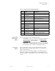
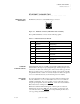
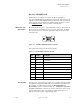
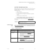
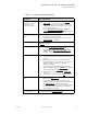
Table Of Contents
- Table of Contents
- Introduction
- Installation and Setup
- Operations
- In This Chapter
- Introduction to Operations
- Setting Output Format
- Testing Outputs
- Selecting an Input Source
- Enabling and Disabling Outputs
- Understanding Auto Sync
- Cropping an Image
- Zooming an Image
- Panning an Image
- Sizing the Output Image
- Using Position
- Adjusting Brightness and Contrast
- Adjusting Hue and Saturation
- Adjusting Sharpness
- Creating a Background
- Creating a 2x2 Monitor Wall
- Command Line Interface
- Image Concepts
- Communications Setup
- Connector Types
- Firmware Upgrades and Troubleshooting
- Technical Specifications

CONNECTOR TYPES
RS-232 Connector
350-7951 Quadra User’s Guide 105
. . . . .
. . . . . . . . . . . . . . . . . . . . . . . . . . . . .
RS-232 CONNECTOR
The RS-232 port is configured according to the Electronic Industries
Association Standard RS-232-C published in August 1969. The Quadra can be
explicitly controlled with ASCII Command Set instructions sent via the RS-232
serial port from either a computer or an ASCII terminal. In Chapter 4, refer to
the “Command Set List
” section for details on all commands.
CONNECTOR TYPE
. . . . . . . . .
AND PINOUTS
Physically, the RS-232 port is a 9-pin D-Sub female connector. The pins for the
RS-232 connector are numbered from top to bottom, right to left. Looking at
the connector, pin #1 is located in the upper right corner, and pin #9 is in the
lower left corner.
Figure C-6.
9-pin D-Sub RS-232 Female Connector
The 9-pin D-Sub connector has the following signals:
. . . . . . . . .
NULL MODEM
You may need to connect Quadra’s serial port to a computer configured as Data
Communications Equipment (DCE). This is accomplished using a null modem.
The net effect of a null modem is to reverse the Transmitted Data and
Received Data connections within the cable. Also, the Request to Send (RTS)
and Clear to Send (CTS) connections are reversed. This may be done by using
a special “null modem” cable, or by inserting a small “null modem” box or
cable in series with a regular “straight through” cable.
Table C-6.
RS-232 Serial Connector Pinouts
Pin Circuit Description
1 CD Carrier Detect
2 TD Transmit Data
3 RD Received Data
4 (not connected)
5 AB Signal Ground (common return)
6 DSR Data Set Ready
7 CTS Clear to Send
8 RTS Request to Send
9 (not connected)
Holes
15
96