
Quadra User's Guide
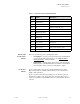
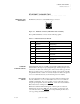
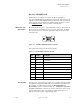
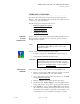
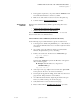
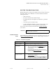
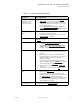
Table Of Contents
- Table of Contents
- Introduction
- Installation and Setup
- Operations
- In This Chapter
- Introduction to Operations
- Setting Output Format
- Testing Outputs
- Selecting an Input Source
- Enabling and Disabling Outputs
- Understanding Auto Sync
- Cropping an Image
- Zooming an Image
- Panning an Image
- Sizing the Output Image
- Using Position
- Adjusting Brightness and Contrast
- Adjusting Hue and Saturation
- Adjusting Sharpness
- Creating a Background
- Creating a 2x2 Monitor Wall
- Command Line Interface
- Image Concepts
- Communications Setup
- Connector Types
- Firmware Upgrades and Troubleshooting
- Technical Specifications
CONNECTOR TYPES
DVI-I Connector
350-7951 Quadra User’s Guide 103
. . . . .
ANALOG AND
DIGITAL INPUT
. . . . . . . . .
CABLES
Please note the following points regarding input cables:
• Analog Inputs — Quadra provides a standard 15-pin sub-miniature D
connector for the analog input signals (see the “High Resolution
Analog Connector” section for details).
• Digital Inputs — Digital graphics inputs can be connected using the
DVI input option. Standard DVI cables are available commercially for
various lengths to allow connection to DVI graphics outputs.
DVI OUTPUT
. . . . . . . . .
CABLES
Quadra’s DVI output connectors support both digital and analog outputs.
Purpose-built cables are available commercially to provide connections for
digital or analog interfaces.
Quadra is provided with a DVI 15-pin adapter for use with analog devices.
Alternatively, an analog-only output cable can be purchased that provides a
“break out” capability to separate RGB connectors or sub-miniature 15-pin D
connector.
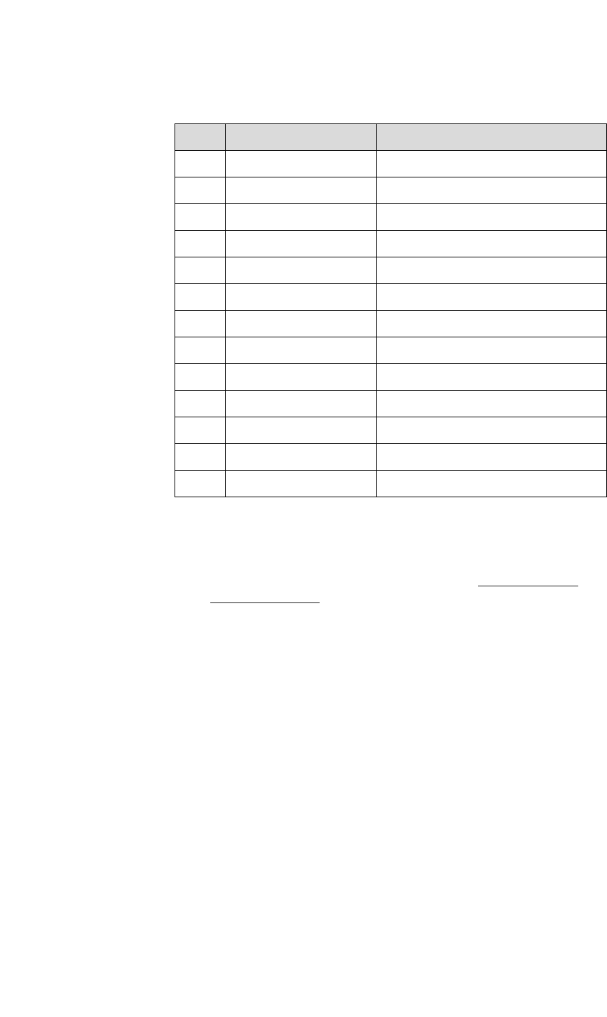
17 TMDS Data 0-
18 TMDS Data 0+
19 TMDS Data 0/5 shield
20 NC Defined for Dual Link only
21 NC Defined for Dual Link only
22 TMDS Clock shield
23 TMDS Clock+
24 TMDS Clock-
C1 Analog Red Red signal
C2 Analog Green Green signal
C3 Analog Blue Blue signal
C4 Analog H sync Analog Horizontal Sync signal
C5 Analog Ground Common analog ground (R,G,B, sync)
Table C-4. DVI-I Connector Pinouts(Continued)
Pin Signal Description