
Quadra User's Guide
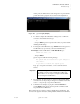
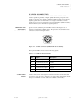
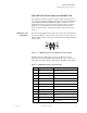
Table Of Contents
- Table of Contents
- Introduction
- Installation and Setup
- Operations
- In This Chapter
- Introduction to Operations
- Setting Output Format
- Testing Outputs
- Selecting an Input Source
- Enabling and Disabling Outputs
- Understanding Auto Sync
- Cropping an Image
- Zooming an Image
- Panning an Image
- Sizing the Output Image
- Using Position
- Adjusting Brightness and Contrast
- Adjusting Hue and Saturation
- Adjusting Sharpness
- Creating a Background
- Creating a 2x2 Monitor Wall
- Command Line Interface
- Image Concepts
- Communications Setup
- Connector Types
- Firmware Upgrades and Troubleshooting
- Technical Specifications
CONNECTOR TYPES
DVI-I Connector
350-7951 Quadra User’s Guide 102
. . . . .
. . . . . . . . . . . . . . . . . . . . . . . . . . . . .
DVI-I CONNECTOR
The DVI connector is used to interconnect graphics devices. This is a standard
connector based on the work of the Digital Display Working Group (DDWG).
CONNECTOR TYPE
. . . . . . . . .
AND PINOUTS
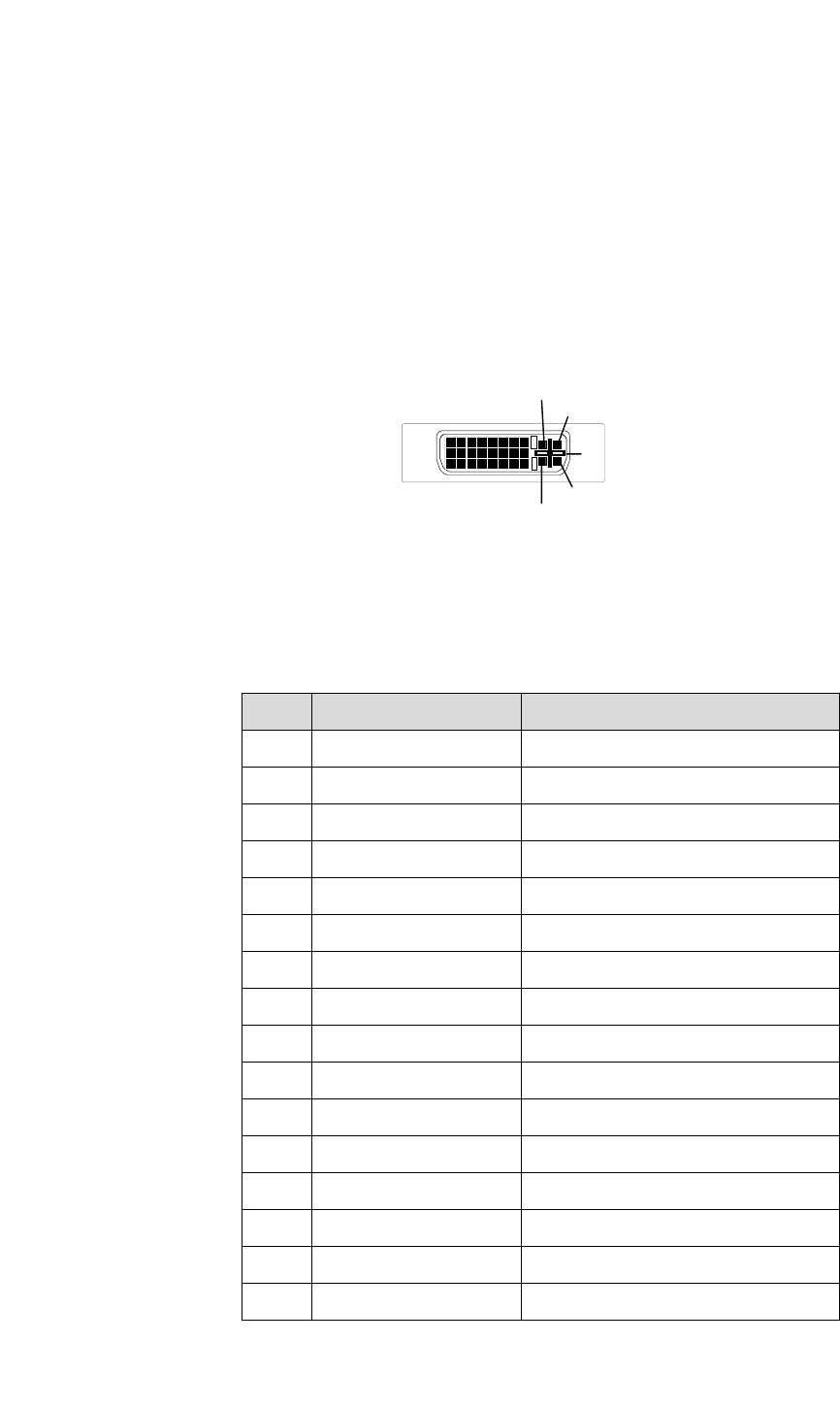
The connector used in Quadra is a 29-pin DVI-I connector, supporting both
analog and digital signals. The DVI-I connector (as shown below) is used for
Quadra’s four standard DVI output channels and for each channel’s optional
digital DVI input.
Figure C-4.
DVI-I Digital/Analog Connector (viewed from rear of chassis
The 29-pin DVI-I connector has the following signals:
Table C-4.
DVI-I Connector Pinouts
Pin Signal Description
1TMDS Data 2-
2TMDS Data 2+
3 TMDS Data 2/4 shield
4 NC Defined for Dual Link only
5 NC Defined for Dual Link only
6 DDC Clock
7 DDC Data
8 Analog Vertical Sync Horizontal sync is on pin C4
9TMDS Data 1-
10 TMDS Data 1+
11 TMDS Data 1/3 shield
12 NC Defined for Dual Link only
13 NC Defined for Dual Link only
14 +5V Power 5 V fused @ 300mA.
15 Ground
16 Hot Plug detect
1
17
9
8
24
C1
C2
C3
C4
C
5