
Quadra User's Guide
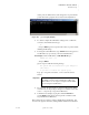
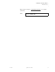
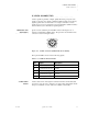
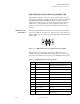
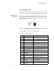
Table Of Contents
- Table of Contents
- Introduction
- Installation and Setup
- Operations
- In This Chapter
- Introduction to Operations
- Setting Output Format
- Testing Outputs
- Selecting an Input Source
- Enabling and Disabling Outputs
- Understanding Auto Sync
- Cropping an Image
- Zooming an Image
- Panning an Image
- Sizing the Output Image
- Using Position
- Adjusting Brightness and Contrast
- Adjusting Hue and Saturation
- Adjusting Sharpness
- Creating a Background
- Creating a 2x2 Monitor Wall
- Command Line Interface
- Image Concepts
- Communications Setup
- Connector Types
- Firmware Upgrades and Troubleshooting
- Technical Specifications
CONNECTOR TYPES
High Resolution Analog Connector
350-7951 Quadra User’s Guide 100
. . . . .
. . . . . . . . . . . . . . . . . . . . . . . . . . . . .
HIGH RESOLUTION ANALOG CONNECTOR
Analog graphics signals are connected to Quadra using a standard 15-pin D-
type connector. In graphics applications, the signals are typically transmitted as
separate Red (R), Green (G) and Blue (B) signals. Sometimes, television
signals are transmitted in component form, but they typically use a different
signal format — using brightness (Y) and color difference signals (U,V).
Quadra accepts either type of signal from the high resolution analog input
connector.
CONNECTOR TYPE
. . . . . . . . .
AND PINOUTS
The high resolution (RGB / YUV) inputs are connected using a sub miniature
15-pin D-type (HD-15), as shown below. This connector is often referred to as
a VGA or VESA connector, and it supports the VGA, SVGA, XGA, SXGA and
UXGA signals.
Figure C-3.
RGB Analog Connector (viewed from rear of chassis)
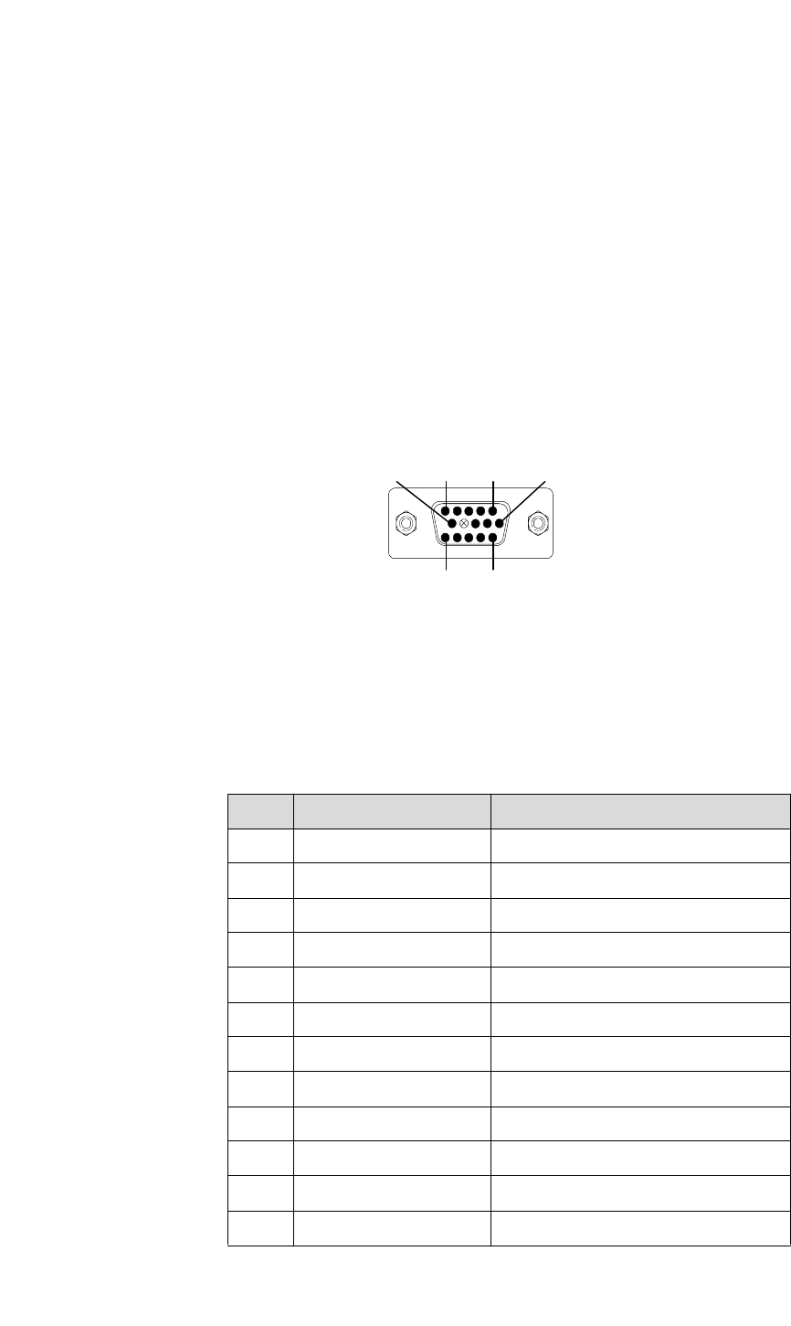
The table below lists signals for the 15-pin D-type (HD-15) connector,
including the pinout for the RGB analog input and the correct connections for
YUV inputs. Note that the analog input supports both RGB and YUV signals.
Table C-3.
RGB Analog Video Connector Pinouts
Pin Signal Description
1 R Red signal (alternatively used for V)
2 G Green signal (alternatively used for Y)
3 B Blue signal (alternatively used for U)
4 NC ID2 (not used)
5 NC GND TEST
6 Ground Red ground
7 Ground Green ground
8 Ground Blue ground
9 no pin (key)
10 Chassis ground Ground
11 NC ID 0 (not used)
12 NC ID1 (not used)
Holes
15
15 11
1
0
6