
Quadra User's Guide
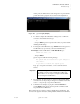
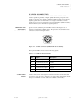
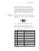
Table Of Contents
- Table of Contents
- Introduction
- Installation and Setup
- Operations
- In This Chapter
- Introduction to Operations
- Setting Output Format
- Testing Outputs
- Selecting an Input Source
- Enabling and Disabling Outputs
- Understanding Auto Sync
- Cropping an Image
- Zooming an Image
- Panning an Image
- Sizing the Output Image
- Using Position
- Adjusting Brightness and Contrast
- Adjusting Hue and Saturation
- Adjusting Sharpness
- Creating a Background
- Creating a 2x2 Monitor Wall
- Command Line Interface
- Image Concepts
- Communications Setup
- Connector Types
- Firmware Upgrades and Troubleshooting
- Technical Specifications
CONNECTOR TYPES
S-Video Connector
350-7951 Quadra User’s Guide 99
. . . . .
. . . . . . . . . . . . . . . . . . . . . . . . . . . . .
S-VIDEO CONNECTOR
S-Video signals are generally of higher quality than analog composite video
signals. Composite video signals combine the black and white (monochrome)
signals together with color information on a single coaxial cable. S-Video
signals, however, use two signal wires to keep the luminance (black and white)
and chrominance (color information) signals separated.
CONNECTOR TYPE
. . . . . . . . .
AND PINOUTS
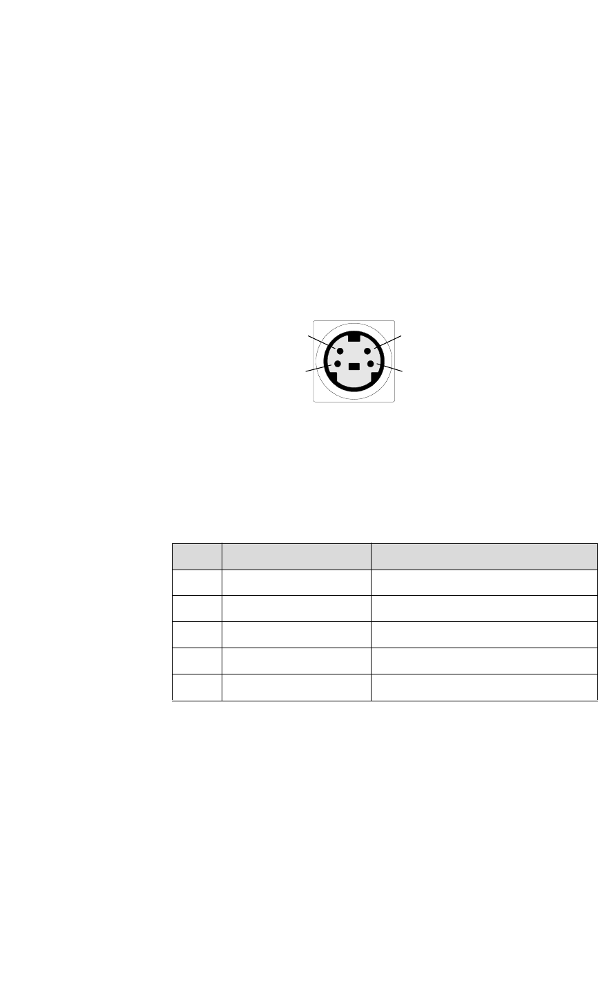
Quadra uses the standard 4-pin mini-DIN connector allowing the use of
standard, commercially available cables. The pinout for the standard S-Video
connector is shown in the figure below:
Figure C-2.
S-Video connector (viewed from rear of chassis)
The 4-pin mini-DIN connector has the following signals:
S-VIDEO CABLE
. . . . . . . . .
LENGTH
S-Video cables tend to have higher loss than the standard coaxial cables (that
are used for composite video). Therefore, for best results, cable lengths should
be kept to a minimum. S-Video cables are available commercially.
Table C-2.
S-Video Connector Pinouts
Pin Signal Description
1 Y (Luminance) Ground Y shield
2 C (Chrominance) Ground C shield
3 Y (Luminance) Signal Y signal
4 C (Chrominance) Signal C signal
Shield Chassis ground Ground
43
12