
User's Manual Part 3


DSPbR Series – User’s Manual
Document Number 00000.B Page 57/75
The “EXT REF” SMA (F) connector is used to lock the internal reference clock with an external 10MHz
reference. The required stability of this reference is +/- 3PPM with a nominal input signal level of 0dBm (0.22V
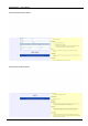
RMS into 50 Ohms). The user via a tick box using the GUI interface under the Systems Configuration page
enables this function. If the external reference does not lock the internal reference clock with the enable function
activated via the GUI tick box, a minor alarm will be raised.
The “REF MON” SMA (F) connector provides a 10MHz reference low impedance signal output at a nominal
0dBm. The output is daisy chained through each Ref Gen module that requires the clock reference. When daisy
chained the Ref Gen modules will buffer the 10 MHz reference prior to forwarding onto the next module.
Cell modem installation and configuration.
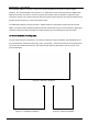
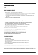
The cell modem fitted onto the Ref Gen + Aux board is optional and can be retrofitted. The DSPbR will have to
be powered down by switching off the supply power. The Ref Gen + Aux board can then be unscrewed from the
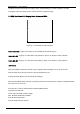
rear of the sub rack frame and removed. The multi-band cell modem is fitted into the multi-pin socket on the
board as illustrated.
Figure 24 – Ref Gen + Aux Board
Figure 25 – Cell Modem Installation
Figure 26 – SIM Card Installation