
User's Manual Part 4


DSPbR Series – User’s Manual
Document Number 00000.B Page 69/75
A: Yes, this is possible, not only in the same band but in two different bands, i.e. where frequency translating is
used. Please note that the bolted on BPFM has to correspond.
Setting the Uplink and Downlink RFBE RF output power levels
Q: Can the RF output power levels of any channel be set within a dB?
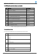
A: Yes! The incremented RF output power levels on any channel can be adjusted in 1dB steps from +30dBm to
+45dBm. When an internal 8-Ch Combiner Filter Unit is fitted, this power level is adjusted according to the
provided table under Chapter 3.3.7 RFBE Back End Module of this User’s Manual
Q: Is the indicated level in dBm via the GUI, the actual output power level at the external connector at the rear
of the DSPbR?
A: No! This indicated power level is the output from the RFBE module within a +/- 0.5dB margin. This level is
then fed either via the TLM (Through Line Module) or BPFM (Band Pass Filter Module) with the respective
losses, which have to be added to estimate the output power at the rear of the DSPbR.
TLM approximate loss – 0.25dB, BPFM approximate loss – 1.2dB. Should an internal combiner module be
used, this would add an additional +/- 11dB of loss to the RFBE output figure.
Ref Gen + Aux
GPS Receiver
Q: How can it be ascertained whether the GPS clock reference disciplining has been activated and locked?
A: When an active GPS antenna is connected to the appropriate SMA (F) port on the Ref Gen + Aux module,
the connection is auto-sensed. Should there be no GPS disciplining of the reference clock, a minor alarm will be
raised.
Q: Is it possible to locate the DSPbR's position in the field via the GPS Receiver.
A: This facility has not been facilitated within the current DSPbR version.
External 10MHz clock reference:
Q: How is the external 10MHz clock reference initiated and checked to see if it is locking the clock reference?
A: The external 10MHz signal reference is enabled via the Web browser GUI interface on the Systems
Configuration page. Should the tick box be ticked and a locked signal not evident, then a minor alarm will be
raised.
Q: How is the 10MHz clock reference carried to the Ref Gen + Aux modules of additional “Slave” sub rack
frames?
A: Using a 50 Ohm coaxial jumper cable +/- 500mm in length terminated with SMA Male connectors. These are
daisy chained Ext Ref input to output.