
User's Manual Part 4


DSPbR Series – User’s Manual
Document Number 00000.B Page 64/75
No special tools are required to remove the plastic fan covers and dust filters. A mild soap wash and dry should
be sufficient to clean the dust filters. Should they be perished in any way, please replace them. The fan dust
filter part number is located under the part number section of this user manual.
9.6 RF input and output port identification
It is very important to identify and mark for future reference the input ports on the BPF / RFFE modules and
output ports of the RFBE / BPFM’s.
These ports are allocated during the uplink and downlink channel configuration procedure via the GUI; refer to
the Individual uplink and downlink channel configuration pages. A better understanding of the configuration
options in terms of slot architecture is detailed in examples given in annexure A.
The configured port allocations can be viewed on the Individual channel status pages.
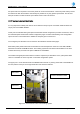
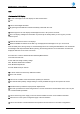
Removable yellow plastic label cards are inserted into recessed apertures at the rear of the DSP, BPFM’s
attached to the RFFE and RFBE modules. This marking system has also been made available on the TLM
modules where they are used in the place of BPFM’s for the RFBE’s.
Use a black fine tipped permanent marker to write the respective port allocations on the yellow plastic label
cards. It is advisable to do this only after a successful configuration upload.
The upper port is on the left hand side of the BPFM module is Side “A” (looking at the back of the DSPR from
the rear) and the lower port on the right hand side of the module is Side “B”
Figure 29 – User Defined Yellow Label Marking System
Side A Port
Side B Port
PLASTIC MARKING LABEL