
Data Sheet

© RFbeam Microwave GmbH
|
Schuppisstrasse 7
|
CH-9016 St. Gallen
|
www.rfbeam.ch
|
K-LD7
|
data sheet 12/2020 - Revision B
Page 8 / 23
APPLICATION INFORMATION
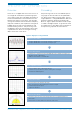
Stand-alone operation
With standard settings the sensor is optimized for
indoor detection of persons. The K-LD7 features four
digital outputs which can directly be used without the
need of an MCU. The digital outputs are per default
configured in the following way:
Pin. No. Name Config Description
2 Digital out 0 Detection Digital detection output. Goes to high if the detection algorithm finds a target in front of the sensor
thatisinthe range up to 5m.
6 Digital out 1 Direction This pin signals the direction of the detected target.
Low backward/receding movement
High forward/approaching movement
This output is only valid together with a high on pin 2
7 Digital out 2 Angle This pin signals if the angle of the detected target is on the left or right side of the sensor.
Low Target on the left side
High Target on the right side
This output is only valid together with a high on pin 2
8 Digital out 3 Range This pin signals if the distance of the detected target is in the near field of the sensor.
Low Target distance higher than 1m
High Target distance lower than 1m
This output is only valid together with a high on pin 2
Table 2: Default digital output description
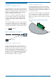
With these settings it is easy to use the sensor
stand-alone as a distance triggered movement de-
tector with direction recognition, near field option and
including the information if the detection was on the
left or right side of the sensor. All these settings can
be also adjusted by the user as described in the next
chapters.
The K-LD7 can also be factory configured
withyour settings. Contact RFbeam for more
information.
Host driven operation
With a connection of the serial interface to a host
(for example MCU or PC) it is possible to read out
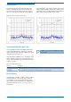
thecomplete processing data (RADC, RFFT, PDAT,
TDAT and DDAT) and control all the parameters
ofthesensor. This is the recommended use case
and allows the user to optimize the sensor easily
for different applications.
The use of the highest baud rate is only recom-
mended to read out data intensive messages
like the RADC and RFFT package.
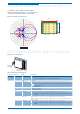
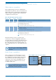
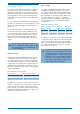
K-LD7 Host
Digital out 0
Digital out 1
Input or INT
Input or INT
Input or INT
Input or INT
Digital out 2
Digital out 3
RXTX
TXRX
optional
Figure 8: MCU or PC connection example