
Data Sheet

© RFbeam Microwave GmbH
|
Schuppisstrasse 7
|
CH-9016 St. Gallen
|
www.rfbeam.ch
|
K-LD7
|
data sheet 12/2020 - Revision B
Page 5 / 23
THEORY OF OPERATION
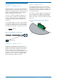
Overview
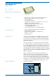
The K-LD7 is a Doppler radar sensor and consists of
an analogue RF frontend and a powerful signal pro-
cessor with tracking and a fully digital serial interface.
The RF frontend features one transmitter with a mo-
dulation input and two I/Q receivers. The signal pro-
cessing unit modulates the frontend with a frequency
step (FSK modulation) and samples the analogue I/Q
Doppler signals for both transmit frequencies and
for both receiving antennas. The processing of this
sampled data allows the measurement and tracking
of speed, direction, distance and angle of moving
objects in the front of the sensor.
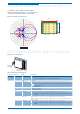
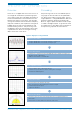
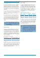
Processing
The processing of the K-LD7 uses different proces-
sing stages to measure and track the speed, direc-
tion, distance and angle of moving targets. The last
stage implements a configurable detection filter which
generates a detection based on parameters like
distance, angle or speed. The detection filter output
is routed to the digital outputs. To get the full control
in an application it is possible to read out the data of
each processing step over the serial interface.
Raw ADC data (RADC)
– Samples I/Q ADC data of receiver Rx1 and Rx2 for frequency A
– Samples I/Q ADC data of receiver Rx1 for frequency B
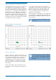
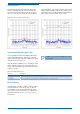
Raw FFT data (RFFT)
– Calculates the complex FFT from the I/Q ADC data of Rx1 andRx2 for frequency A
– Averages the two complex FFT’s
– Adds the threshold line to the RFFT data
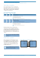
Raw target data (PDAT)
– Search all targets above a threshold in the FFT
– Calculates the speed, direction, distance and angleofeach target
– Generates the PDAT target list
Tracking data (TDAT)
– Cluster and track the dominant raw target
– Filter out interferences generated by fans or fluorescent light
– Predicts temporary lost objects
– Suppresses vibrations
Detection data (DDAT)
– Generates a detection if the tracked target matches the programmed detection
filtercriteria
– Check if there is a micro detection in the front of the sensor
Figure 4: Signal processing workflow