
Data Sheet

© RFbeam Microwave GmbH
|
Schuppisstrasse 7
|
CH-9016 St. Gallen
|
www.rfbeam.ch
|
K-LD7
|
data sheet 12/2020 - Revision B
Page 4 / 23
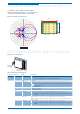
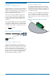
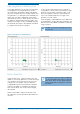
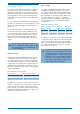
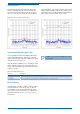
ANTENNA DIAGRAM CHARACTERISTICS
This diagram shows module sensitivity in both
azimuth and elevation directions. It incorporates the
transmitter and receiver antenna characteristics.
Figure 2: Antenna characteristics
80°
34°
Rx1 Rx2 Tx
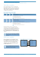
PIN CONFIGURATION AND FUNCTIONS
Figure 3: Pin configuration
X1 Pin1
(3x2.54)
X2 Pin1
(8x2.54)
25
38
20.8
0
2.37
34.63
18.5
12.5
B
0.74
0
6
11.2
2.3
0.64
0.64
B (4:1)
D
C
B
6
5
4
3
2
1
2
1
4
3 5
B
A
C
7
8
E
F
7
6
E
D
Plotdate 14.08.2019
10
9
11
12
8
9
10
11
H
G
F
G
We reserve all rights in this document and its subject matter.
The recipient herby acknowledges these rights and assures the use of this
document only for the purpose it was delivered. © RFbeam Microwave
Dieses Dokument ist unser geistiges Eigentum. Es darf ohne unsere ausdrückliche Genehmigung
weder kopiert, vervielfältigt oder verwertet, noch an Dritte weitergegeben werden. Zuwiderhandlung
ist strafbar und wird strafrechtlich verfolgt. Copyright reserved! © RFbeam Microwave
A
Drawing Nr.
A2
1 / 1
Blatt / Anz.
Project
Scale
2:1
Material
Tolerance
Format
Prepared
Reviewed
Object
Surface
RFbeam Microwave
Schuppisstrasse 7
9016 St. Gallen
Switzerland
State
Index
XX
YY
XX
YY
Connector Pin. No. Name Description
X1 1 – 3 Mounting These pins are for mounting only.
Leave this pins floating and do not connect them to any potential.
X2 1 GND Ground pin
2 Digital out 0 Digital detection output. Goes to high if the detection algorithm finds a target in front of the sensor.
The detection area and other parameters of the detection algorithm can be easily changed over
the instruction set.
3 VCC Power supply pin (3.2 to 5.5V)
4 RX Serial interface RX input
5 TX Serial interface TX output
6 Digital out 1 Digital miscellaneous output 1. The function is programmable over the instruction set.
This output is only valid together with a high on pin 2 except if it is configured as micro detecti-
on output.
7 Digital out 2 Digital miscellaneous output 2. The function is programmable over the instruction set.
This output is only valid together with a high on pin 2 except if it is configured as micro detecti-
on output.
8 Digital out 3 Digital miscellaneous output 3. The function is programmable over the instruction set.
This output is only valid together with a high on pin 2 except if it is configured as micro detecti-
on output.
Table 1: Pin function description
-70
-60
-50
-40
-30
-20
-10
0
350°
340°
330°
320°
310°
300°
290°
280°
270°
260°
250°
240°
230°
220°
210°
200°
190°
180°
170°
160°
150°
140°
130°
120°
110°
100°
90°
80°
70°
60°
50°
40°
30°
20°
10°
0°
System diagram
Azimuth Elevation