
Data Sheet

© RFbeam Microwave GmbH
|
Schuppisstrasse 7
|
CH-9016 St. Gallen
|
www.rfbeam.ch
|
K-LD7
|
data sheet 12/2020 - Revision B
Page 18 / 23
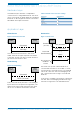
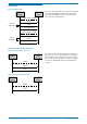
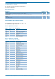
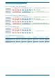
Table 14: Application commands
Commands
This chapter provides detailed information about
thecommands.
Header Payload Length Description Values
INIT 4 Start of connection 0 = 115200, 1 = 460800, 2 = 921600, 3 = 2000000, 4=3000000
GNFD 4 Get next frame data Binary coded bit-field. 0 = disabled, 1 = enabled
0x01 = RADC, 0x02 = RFFT, 0x04 = PDAT, 0x08 = TDAT,
0x10 = DDAT, 0x20 = DONE
GRPS 0 Get radar parameter structure –
SRPS 42 Set radar parameter structure See chapter “Parameter structure” for details
RFSE 0 Restore factory settings –
GBYE 0 Disconnect –
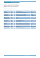
RBFR 4 Base frequency 0 = Low, 1 = Middle, 2 = High
RSPI 4 Maximum speed 0 = 12.5 km / h, 1 = 25 km / h, 2 = 50 km / h, 3 = 100 km / h
RRAI 4 Maximum range 0=5m, 1=10m, 2=30m, 3=100m
THOF 4 Threshold offset 10 – 60 dB
TRFT 4 Tracking filter type 0 = Standard, 1 = Fast detection, 2 = Long visibility
VISU 4 Vibration suppression 0-16, 0 = No suppression, 16 = High suppression
MIRA 4 Minimum detection distance 0 – 100 % of range setting
MARA 4 Maximum detection distance 0 – 100 % of range setting
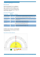
MIAN 4 Minimum detection angle -90° to +90°
MAAN 4 Maximum detection angle -90° to +90°
MISP 4 Minimum detection speed 0 – 100 % of speed setting
MASP 4 Maximum detection speed 0 – 100 % of speed setting
DEDI 4 Detection direction 0 = Receding, 1 = Approaching, 2 = Both
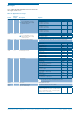
RATH 4 Range threshold 0 – 100 % of range setting
ANTH 4 Angle threshold -90° to +90°
SPTH 4 Speed threshold 0 – 100 % of speed setting
DIG1 4 Digital output 1 0 = Direction, 1 = Angle, 2 = Range, 3 = Speed, 4 = Micro detection
DIG2 4 Digital output 2 0 = Direction, 1 = Angle, 2 = Range, 3 = Speed, 4 = Micro detection
DIG3 4 Digital output 3 0 = Direction, 1 = Angle, 2 = Range, 3 = Speed, 4 = Micro detection
HOLD 4 Hold time 1 – 7200 s
MIDE 4 Micro detection retrigger 0 = Off, 1 = Retrigger
MIDS 4 Micro detection sensitivity 0-9, 0=Min. sensitivity, 9=Max. sensitvity