Eclipse Series T70/T150 Transmitter Operation and Maintenance RF TECHNOLOGY PTD.
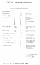
TTO/T150 « Operation and Maintenance CONTENTS Page Operas Instructions 5 internal Jumper Options 7 1/0 Connections 8g Program 9 Circuit Scripted io Alignment Procedures 15 specifications Appendix A Parts List MHz Power Amplifier 32 136 -174 Mhz Power Amplifier 33 Board Layout Exciter 34 66 B88 MHz Power Amp 35 136 -174 Mhz Power Amp 36 RE TECHNOLOGY PTD. LTD FCC I BERETTA JOR #18200 EXHIBIT 5 RF Technology Pty. Lid.
T7O/T150 ~ Operation and Maintenance Operating Instructions PTT The PTT button is used to key the transmitter during system test and adjustment. Audio from the line input is automatically disabled so that an modulated carrier with sub audible tone Is transmitted, LINE The LINE trim pot is used to set the line and direct audio input level, Its normally set to give 60% of system deviation with 0 dBm (775 mV) input at 1 KHz.
T70/T480 « Operation and Maintenance For transmitters using issue number 4 or lower the alarm condition is indicated by the flash rate.
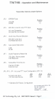
T7OIT150 Operation and Maintenance Transmitter Internal Jumper Options Pa. PROM Type Position 270258 2-37 27064 1-2 JPaB00 Ohm Line de Loop PTT Input Position de Loop Connected 1-2 * de Loop Not Connected 2-3 JP4 Audio Input Source Selection Position 600 Ohm Line Input 2-3 Hi-Z Balanced Input 1-2 JRE Input Level Attenuation Position 0dB 2-3" Audio Frequency Response Position 750 u Sec. Pr-emphasis 1-2 Flat Response 2-3 JP8Subiaudible Tone Source Position Internal CSS 2.
TTOT150 Operation and Maintenance T70/T180 Transmitter JO Connections Functionalist de Power +12 Vdc -12 Side Channel Selection R§232 Serial Data Input 600 Chm Line High 150 Ohm/Hybrid Connections Direct PTT Input TR Relay Driver Output Hi-Z Audio Input Yoko Sub-Audible Tone Input External ALC Input Specification +11.
T70/T150 Operation and Maintenance Channel and Tone Frequency Programming Channel and tone frequency programming is most easily accomplished with RF. Technology Helpmate software. This software can be run on any BM compatible PC and provides a number of additional useful facilities. Helpmate provides a simple means of calibrating the forward and reverse power detectors and alarms. Helpmate can be supplied by your dealer, distributor or by contacting RF, Technology direct.
T7OIT150 Operation and Maintenance Circuit Description Tha following descriptions should be read as an aid to understanding the block and schematic diagrams at the rear of this manual. VEO Action The Voltage Controlled Oscillator uses a junction FET Q19 which oscillates at the required transmitter output frequency.
TTOT150 Operation and Maintenance Power Amplifier The 10 mW output from the main board connects to the power amplifier board through a short miniature 50 Ohm coaxial cable. (2 on the power amplifier board increases the signal to approximately 200 mW. The bias currant of Q2 is controlled by O11 and the power leveling circuitry fo adjust the drive to the output module U2. U2 increases the power to 30 watts before iris fad to the directional couplet, iow pass filter and output connector.
TTO/T180 « Operation and Maintenance Local Microphone input The local microphone input 1s provided for use with a standard low impedance dynamic microphone. The microphone output iz amplified by USa before connecting to analog switch Ua. L10k inverts the local microphone PTT input to switch U10a ON when the microphone PTT button is passed. {10a is OFF at all other times. The lost microphone audio has priority over the other Inputs.
T70/T180 » Operation and Maintenance PTT and DC Remote Control Two main PTT inputs are provided. The first, a direct logic level input, is connected to pin 3 of the system connector. The transmitter can be keyed by applying a folic low or ground on pin 3. Pin 3 connects to the PTT logic and microprocessor through D0, DC current loop control can be used for remote PTT operation. The current loop can be-configured by JP, JP and JPN for use with either a remote free switch or a remote switched source.
T70/T180 ~ Operation and Maintenance This circuit is short circuit and overload proof by virus of the component currant and power ratings. The maximum current and dissipation rating of the pass transistor can nat be exceeded under any road condition.