
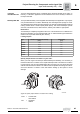
Technical data

Manual – Gear Units and Gearmotors
87
7
Circuit breakers and protective equipment
Project Planning for AC Motors
7.3 Circuit breakers and protective equipment
EMC measures AC motors, AC brake motors and MOVIMOT
®
drives from SEW-EURODRIVE are com-
ponents for installation in machinery and systems. The designer of the machine or
system is responsible for complying with the EMC Directive 89/336/EEC. Please refer
to the publication "Drive Engineering - Practical Implementation, Electromagnetic
Compatibility (EMC) in Drive Engineering" for detailed information about this topic. For
specific information on MOVIMOT
®
drives, refer to the "Drive System for Decentralized
Installation" system manual.
Line voltage opera-
tion, MOVIMOT
®
drives
SEW-EURODRIVE AC (brake) motors satisfy the EMC generic standards EN 50081
and EN 50082 when used in accordance with their designated use in continuous line
voltage operation. Interference suppression measures are not necessary. MOVIMOT
®
drives also satisfy the EMC generic standards EN 50081 and EN 50082 when operated
in accordance with their designated use.
Switching
operation
For switching operation of the motor, take suitable measures for suppressing
interference from the switchgear.
Inverter operation Regarding inverter operation, please refer to the installation and EMC instructions
provided by the inverter manufacturer. Also note the following points:
Brake motors on
the inverter
Install the brake cables of brake motors separately from the other power cables,
maintaining a distance of at least 200 mm (7.87 in). Joint installation is only permitted if
either the brake cable or the power cable is shielded.
Tachometer
connection on the
inverter
Observe the following instructions when connecting the tachometer:
• Use a shielded cable with twisted pair conductors only.
• Connect the shield to the PE potential on both ends over a large surface area.
• Install signal cables separately from power cables or brake cables (min. distance or
200 mm or 7.87 in).
Positive tempera-
ture coefficient
(PTC) thermistor
TF connection on
the inverter
Install the connecting lead of the positive temperature coefficient (PTC) thermistor TF
separately from other power cables, maintaining a distance of at least 200 mm (7.87 in).
Collective installation is only permitted if either the TF cable or the power cable is
shielded.