
Technical data
Manual – Gear Units and Gearmotors
83
6
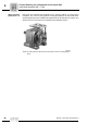
Input shaft assembly AD (→ GK)
Project Planning for Components on the Input Side
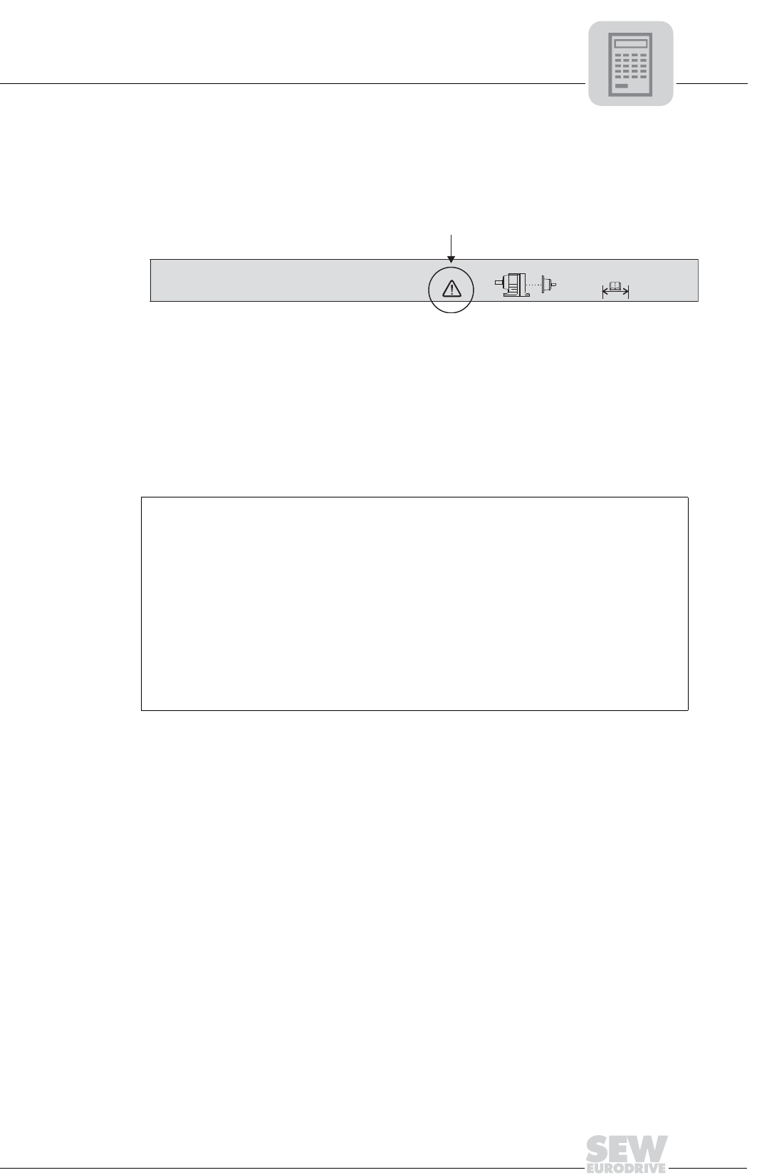
Thermal limit
power for gear
units with input
shaft assembly
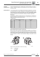
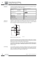
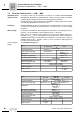
The power values given in the selection tables for gear units with input shaft assemblies
are mechanical limit powers. Depending on the mounting position, however, gear units
may become thermally overloaded before they reach the mechanical power limit.
Relevant cases for mineral oils are identified in the selection tables (see column under
the arrow) by giving their mounting position.
If the required mounting position corresponds with an indicated one, please consult
SEW. By considering the actual operating conditions, it will then be possible to recalcu-
late the thermal limit rating based on the specific application. Alternatively, suitable
measures can be taken (e.g. using a synthetic lubricant with higher thermal stability) to
increase the thermal limit rating of the gear unit. The following data are required for re-
calculation:
50338AUS
Figure 36: Selection table
Gear unit type ....................
Output speed [n
a
]
............... rpm Gear ratio i ..........................
Ambient temperature ............... °F Cyclic duration
factor cdf
..........................%
Power drawn [P] ............... HP
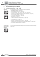
Installation site: .........................................................................................................................
...in small, enclosed rooms
...in large rooms, halls
...outdoors
Installation on site:
.........................................................................................................................
e.g. base made of steel or concrete
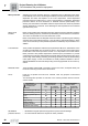
R107 AD... , n
e
= 1750 rpm 4300 lb-in
i n
a
[rpm]
T
a max
[lb-in]
P
e
[HP]
F
Ra
[lb]
F
Re
[lb]
ϕ
(/R)
[ ' ]
m
[lb]