
Technical data
Manual – Gear Units and Gearmotors
81
6
Input shaft assembly AD (→ GK)
Project Planning for Components on the Input Side
Centering
shoulder AD../ZR
The input shaft assembly can be configured with a centering shoulder as an option. In
this way, a customer’s application can be attached to the cover centrally in relation to
the input shaft side.
Backstop AD../RS The input shaft assembly can be supplied with a backstop if the application only requires
one permitted direction of rotation. Backstops with centrifugal lift-off sprags are used.
The advantage of this design is that the sprags move around inside the backstop without
making contact above a certain speed (lift-off speed). This means backstops operate
wear-free, maintenance-free, without losses, and they are suited for high speeds.
Dimensions:
The backstop is completely integrated in the cover. This means there is no difference in
dimensions between an input shaft assembly with or without backstop (see dimension
sheets in the "Input shaft assembly AD" section).
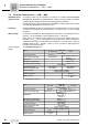
Locking torques:
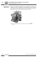
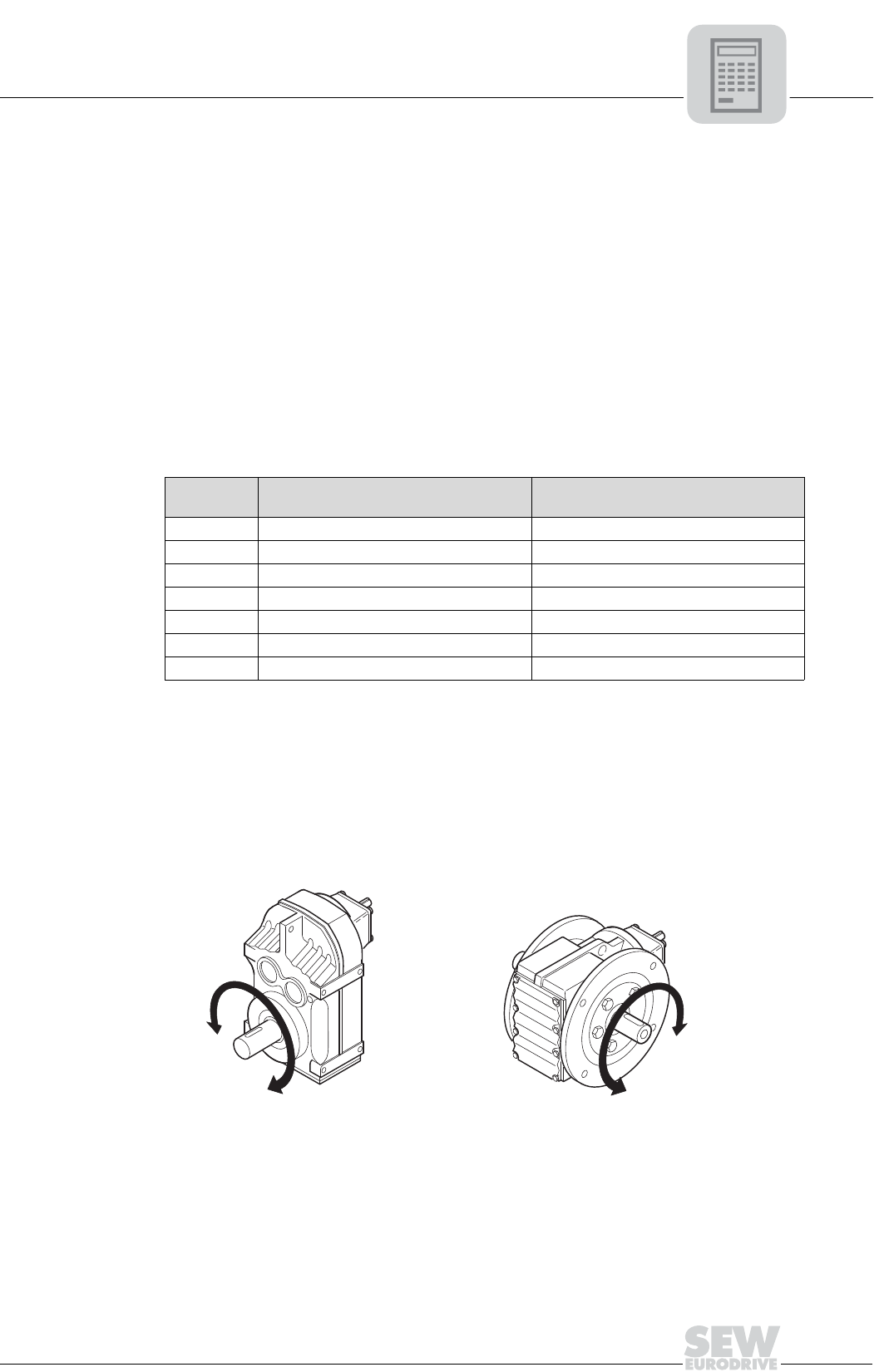
Specify output direction of rotation in your order:
When you order a gear unit with input shaft assembly and backstop, it is necessary to
indicate the direction of rotation of the output shaft/output side. The direction of rotation
is given looking onto the output shaft/output side of the gear unit. For drives with shaft
ends at sides A and B, the direction of rotation must be specified as looking onto side A.
Check the direction of rotation of the drive before starting up the system to avoid
damage.
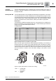
Type Maximum locking torque backstop
[lb-in]
Lift-off speed
[rpm]
AD2/RS 795 640
AD3/RS 3010 600
AD4/RS 6200 550
AD5/RS 10600 630
AD6/RS 12800 430
AD7/RS 12800 430
AD8/RS 25300 430
53722AXX
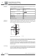
Figure 34: Specify output direction of rotation when ordering
CCW = Counterclock-
wise rotation
CW = Clockwise
rotation
A
B
CCW
CW
CCW
C
W