
Technical data
Manual – Gear Units and Gearmotors
77
6
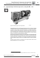
Project planning for helical-bevel gear units on swing base MK (→ GK)
Project Planning for Components on the Input Side
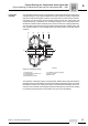
Centrifugal
coupling
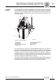
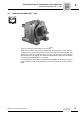
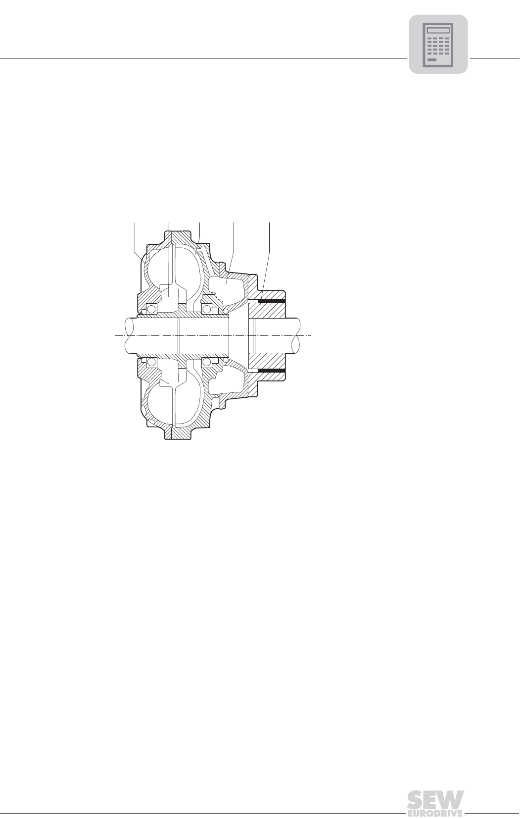
The centrifugal coupling used is a hydrodynamic coupling that operates according to the
Föttinger principle. The coupling is filled with oil and consists of a pump wheel (motor
side) and a turbine wheel (gear unit side). The pump wheel converts the input mechan-
ical energy into fluid energy and the turbine wheel converts this energy back into
mechanical energy. Furthermore, the centrifugal couplings on the swing base have a
deceleration chamber which holds part of the oil volume when the coupling is stationary.
The oil is slowly returned to the pump and turbine wheels during the starting phase. This
has a positive influence on the starting phase and reduces strain on the drive and the
machine.
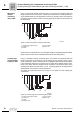
The hydraulic centrifugal coupling is equipped with fusible safety plugs that allow the
operating fluid to be evacuated in the event of excessive temperature (severe overload,
blockage). In this way the coupling and system are protected from damage. We recom-
mend you use a thermal monitoring device (MTS or BTS option) to prevent the coupling
from loosing oil and protect the environment in the event of an oil leakage.
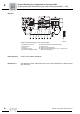
52256AXX
Figure 30: Centrifugal coupling
[1] Pump wheel
[2] Operating fluid (hydraulic oil)
[3] Turbine wheel
[4] Deceleration chamber
[5] Flexible connecting coupling
[A] Gear unit side
[B] Motor side
[1]
A
B
[2]
[3]
[4] [5]