
Technical data
6
74
Manual – Gear Units and Gearmotors
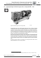
Adapter with hydraulic centrifugal coupling AT (→ GK)
Project Planning for Components on the Input Side
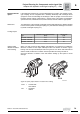
Disc brake
AT../BM(G) option
The adapter with hydraulic centrifugal coupling can be configured with an SEW disc
brake if the machine is to be braked in a defined manner. The brake is an electro-
magnetic disc brake with a DC coil which is released electrically and braked using spring
force. As a result, the brake satisfies the safety requirement of braking in the event of a
power failure. The braking torque can be varied by means of the type and number of
brake springs used. The brake can be supplied with DC or AC voltage connection; the
equipment needed for controlling the brake and the connection terminals are accommo-
dated in a terminal box attached to the adapter. The brake can additionally be equipped
with manual brake release on request.
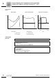
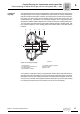
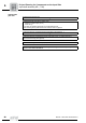
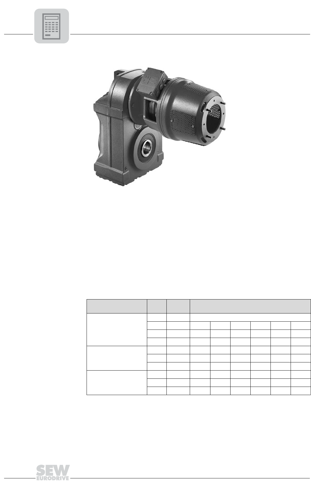
Braking torques
Order information Specify the required braking torque and brake voltage when ordering a gear unit with
adapter, centrifugal coupling and brake. If you do not specify these values in your order,
the maximum permitted braking torque will be set.
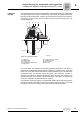
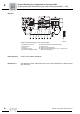
04611AXX
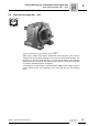
Figure 27: Parallel shaft helical gear unit with adapter AT and disc brake
BM(G)
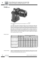
Type
d
rz
1)
[mm]
1) The pinion spigot diameter depends on the gear ratio, please contact SEW-EURODRIVE.
T
Bmax
2)
[lb-in]
2) Maximum braking torque
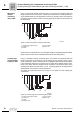
Reduced braking torques (guide values)
[lb-in]
AT311/BMG - AT322/BMG
10 84
12 112 84
16 265 168 112 84
22 485 400 325 265 168 112 84
AT421/BMG - AT422/BMG
16 265 168 112 84
22 485 400 325 265 168 112 84
28 485 400 325 265 168 112 84
AT522/BM - AT542/BM
22 665 445
28 1330 1110 890 665 445
32 2210 1770 1330 1110 890 665 445