
Technical data
Manual – Gear Units and Gearmotors
73
6
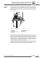
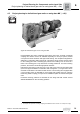
Adapter with hydraulic centrifugal coupling AT (→ GK)
Project Planning for Components on the Input Side
Backstop AT../RS
option
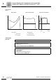
If the application requires only one permitted direction of rotation, the hydraulic centrif-
ugal coupling can be configured with a backstop. Backstops with centrifugal lift-off
sprags are used. The advantage of this design is that the sprags move around in the
backstop without making contact above a certain speed. This means the backstops
operate wear-free, maintenance-free, without losses, and are suited for high speeds.
Dimensions The dimensions of the hydraulic centrifugal coupling with backstop AT../RS are identical
to those of the hydraulic centrifugal coupling AT.. (see dimension drawings in the section
Hydraulic centrifugal coupling AT..).
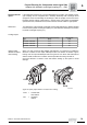
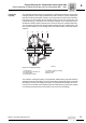
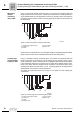
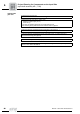
Locking torques
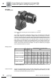
Specify output
direction of rotation
when ordering
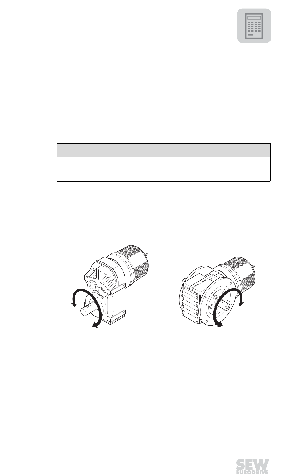
When you order a gear unit with adapter and backstop, it is necessary to indicate the
direction of rotation for the output shaft/output side. The direction of rotation is given
looking onto the output shaft/output side of the gear unit. For drives with shaft ends at
sides A and B, the direction of rotation must be specified as looking onto side A.
Check the direction of rotation of the drive before starting up the system to avoid
damage.
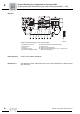
Type
Maximum locking torque backstop
[lb-in]
Lift-off speed
[rpm]
AT311/RS - AT322/RS 3010 600
AT421/RS - AT422/RS 6200 550
AT522/RS - AT542/RS 10600 630
53721AXX
Figure 26: Specify output direction of rotation when ordering
CCW = Counterclock-
wise rotation
CW = Clockwise
rotation
A
B
CCW
CW
CCW
CW