
Technical data
Manual – Gear Units and Gearmotors
67
6
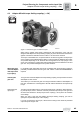
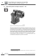
Adapter AR with torque limiting coupling (→ GK)
Project Planning for Components on the Input Side
Slip monitor /WS
option
In conjunction with Varigear
®
variable speed gear units (see Variable Speed Gear Units
catalog), the speed monitor is replaced by a slip monitor for monitoring the speed differ-
ence between the input and output halves of the coupling.
The signal pick-up depends on the size of the variable speed gear unit and consists of
two encoders or one encoder and an AC tachogenerator.
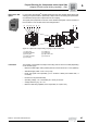
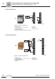
Connection The encoder is connected to the slip monitor using a two or three-core cable (depending
on the encoder type).
• Maximum cable length: 500 m (1640 ft) with a line cross section of 1.5 mm
2
(AWG14)
• Standard supply cable: 3-core / 2 m (6.5 ft)
• Route the signal lines separately (not in multicore cables) and shield them, if
necessary.
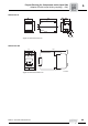
• Enclosure: IP40 (terminals IP20)
• Operating voltage: 110...240 AC/DC (50...60 Hz) or 24V DC
• Voltage tolerance [%]: -20...+10
• Maximum switching capability of the output relay: 6 A (250 V AC)
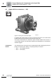
52262AXX
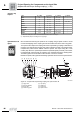
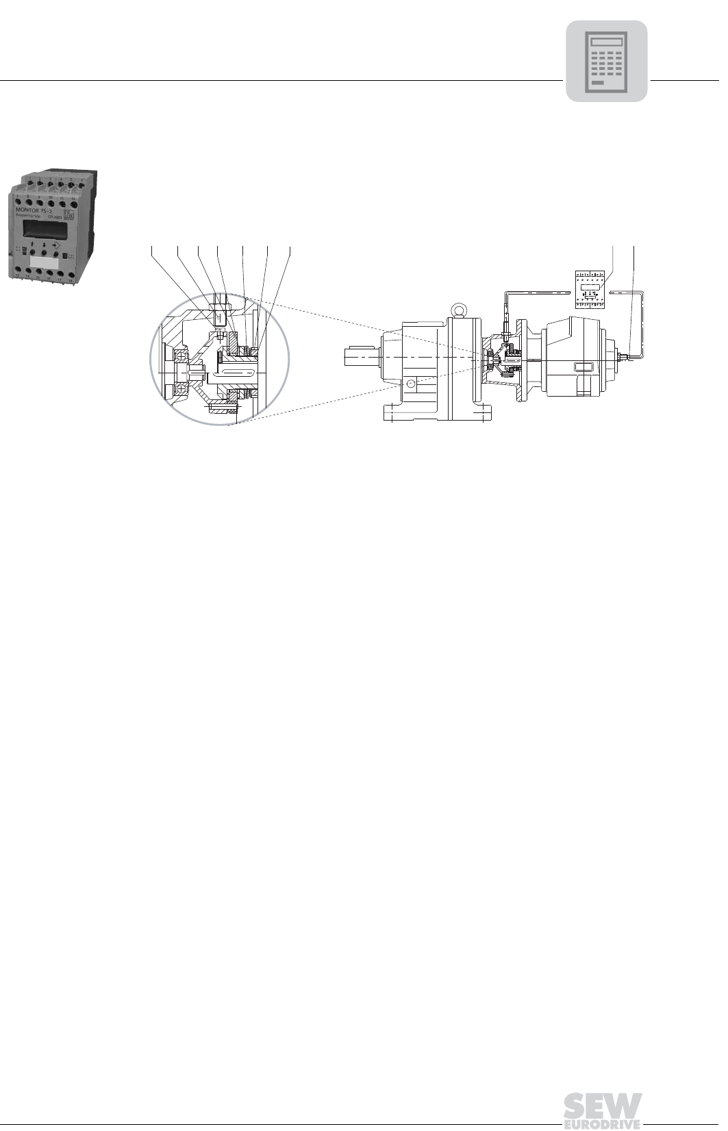
Figure 19: Adapter with a torque limiting coupling and slip monitor /WS
[1] Trigger cam
[2] Encoder (adapter)
[3] Driving disc
[4] Friction ring pads
[5] Cup spring
[6] Slotted nut
[7] Friction hub
[8] Slip monitor /WS
[9] Encoder IG
22 23 24
A1 A2
19
213456
789
10 11 12
13 14 15 16 17 18
20 21
[1]
[2]
[3]
[4] [5] [6] [7] [8] [9]