
Technical data
Manual – Gear Units and Gearmotors
53
5
Overhung and axial loads (→ GM, → MM, → GK)
Project Planning for Gear Units
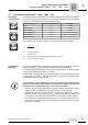
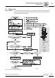
On the input side:
Overhung load
conversion for
off-center force
application
Important: only applies to gear units with input shaft assembly:
Consult SEW-EURODRIVE for off-center force application on the drive end.
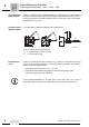
On the output
side: Overhung
load conversion
for off-center
force application
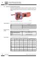
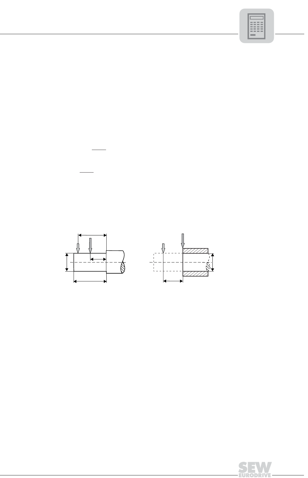
The permitted overhung loads must be calculated according the selection tables using
the following formulae in the event that force is not applied at the center of the shaft end.
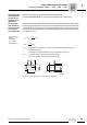
The smaller of the two values F
xL
(according to bearing life) and F
xW
(according to shaft
strength) is the permitted value for the overhung load at point x. Note that the calcula-
tions apply to T
a max
.
F
XL
according to
bearing
service life
F
xW
from the
shaft strength:
F= F
xL Ra
•
a
b + x
[lb]
F=
xW
c • 10
3
f + x
[lb]
F
Ra
= Permitted overhung load (x = l/2) for foot-mounted gear units according to the
selection tables in [lb]
x = Distance from the shaft shoulder to the force application point in [in]
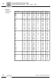
a, b, f = Gear unit constant for overhung load conversion[in]
c = Gear unit constant for overhung load conversion[in]
02356BXX
Figure 11: Overhung load F
x
for off-center force application
x
x
F
Ra
F
Ra
F
X
F
xL
d
d
l
l/2