
Technical data
5
50
Manual – Gear Units and Gearmotors
Service factor
Project Planning for Gear Units
Helical-worm
gear units
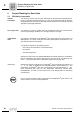
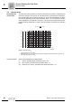
For helical-worm gear units, two additional service factors will have to be taken into
consideration besides service factor f
B
derived from Figure 8 . These are:
•f
B1
= Service factor from ambient temperature
•f
B2
= Service factor from cyclic duration factor
The additional service factors f
B1
and f
B2
can be determined by referring to the diagrams
in Figure 9 . For f
B1
, the load classification is taken into account in the same way as for
f
B
.
The total service factor for helical-worm gear units is calculated as follows:
Example The gearmotor with the service factor f
B
= 1.51 in the previous example is to be a helical-
worm gearmotor.
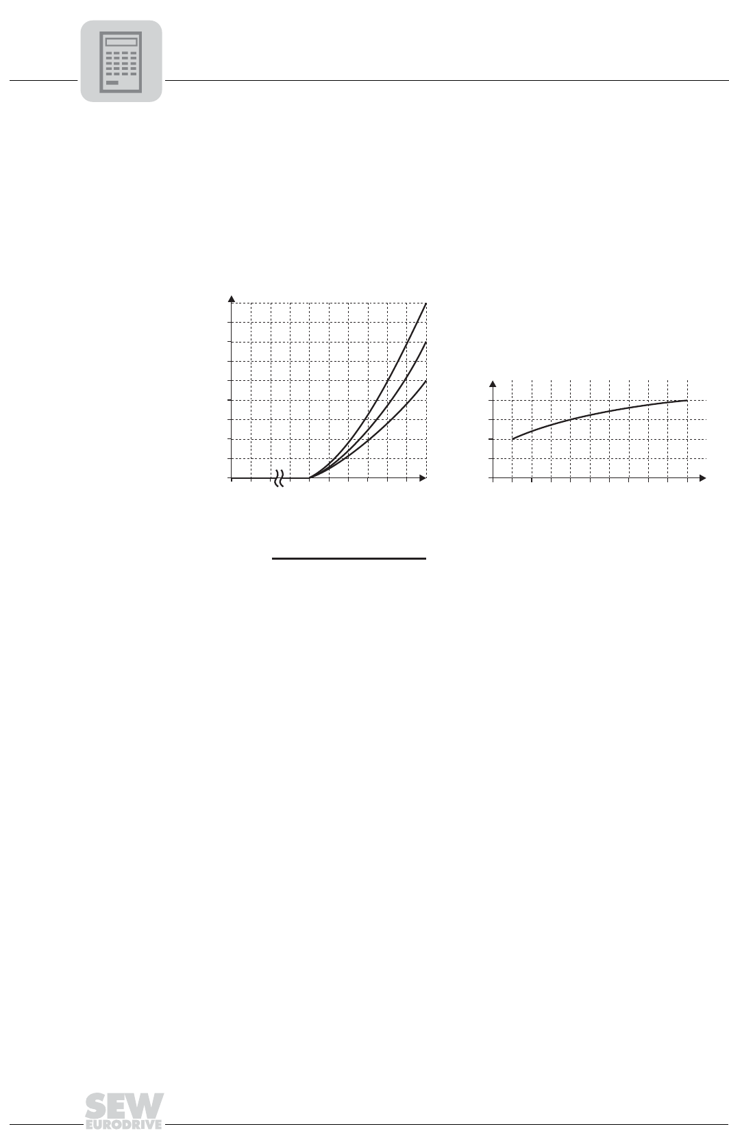
Ambient temperature ϑ = 40°C → f
B1
= 1.38 (read off at load classification II)
Time under load = 40 min/h →cdf = 66.67% → f
B2
= 0.95
The total service factor is f
Bges
= 1.51 • 1.38 • 0.95 = 1.98
According to the selection tables, the selected helical-worm gearmotor must have an
SEW f
B
service factor of 1.98 or greater.
00657BXX
Figure 9: Additional service factors f
B1
and f
B2
Contact SEW-EURODRIVE in case of temperatures below -20 °C (-4 °F) (→f
B1
).
f
Bges
= f
B
• f
B1
• f
B2
f
B2
-20
0
-10
20 40
60
20
80
30
100 %ED
40 50°C
f
B1
1.0
0.6
1.2
0.8
1.4
1.0
1.6
1.8
(III)
(II)
(I)
ED (%) =
Time under load in min/h
60
• 100