
Technical data
Manual – Gear Units and Gearmotors
49
5
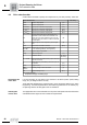
Service factor
Project Planning for Gear Units
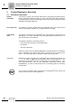
Mass acceleration
factor
The mass acceleration factor is calculated as follows:
"All external mass moments of inertia" are the mass moments of inertia of the driven
machine and the gear unit, scaled down to the motor speed. The calculation for scaling
down to motor speed is performed using the following formula:
"Mass moment of inertia at the motor end" is the mass moment of inertia of the motor
and, if installed, the brake and the flywheel fan (Z fan).
Service factors f
B
> 1.8 may occur with large mass acceleration factors (> 10), high
levels of backlash in the transmission elements or large overhung loads. Contact SEW-
EURODRIVE in such cases.
Service factor:
SEW f
B
The method for determining the maximum permitted continuous torque T
a max
and using
this value to derive the service factor f
B
= T
a max
/ T
a
is not defined in a standard and
varies greatly from manufacturer to manufacturer. Even an SEW service factor of f
B
=
1, the gear units afford an extremely high level of safety and reliability in the fatigue
strength range (exception: wearing of the worm wheel in helical-worm gear units). The
service factor may differ from specifications of other gear unit manufacturers. If you are
in doubt, contact SEW-EURODRIVE for more detailed information on your specific
drive.
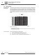
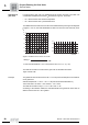
Example Mass acceleration factor 2.5 (load classification II), 14 hours/day operating time (read
off at 16 h/d) and 300 cycles/hour result in a service factor f
B
= 1.51 according to
Figure 8. According to the selection tables, the selected gearmotor must have an SEW
f
B
value of 1.51 or greater.
J
X
J
n
n
M
= Mass moment of inertia scaled down to the motor shaft
= Mass moment of inertia with reference to the output speed of the gear unit
= Output speed of the gear unit
= Motor speed
Mass acceleration factor =
All external mass moments of inertia
Mass moment of inertia on the motor end
J=J
X
()
n
n
M
2