
Technical data

Manual – Gear Units and Gearmotors
43
4
Project planning sequence
Project Planning for Drives
4.3 Project planning sequence
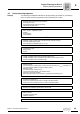
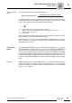
Example The following flow diagram illustrates the project planning procedure for a positioning
drive. The drive consists of a gearmotor that is powered by an inverter.
Necessary information on the machine to be driven
– Technical data and environmental conditions
– Positioning accuracy
– Speed setting range (rotational accuracy)
– Calculating the travel cycle
↓
Calculate the relevant application data
– static, dynamic, regenerative power
– Speeds
– Torque ratings
– Travel diagram
↓
Select gear unit
– Definition of gear unit size, gear unit reduction ratio and gear unit type
– Check the positioning accuracy
– Check the gear unit utilization (T
a max
≥ T
a (t)
)
↓
Select the system depending on
– Positioning accuracy
– Setting range
– Control
↓
Inverter operation
– Voltage-controlled inverter without and with speed control
– Voltage-controlled, vector-controlled inverter without and with speed control
– Current-controlled, vector-controlled inverter
↓
Motor selection
– Maximum torque
– For particularly low output speeds: Limit motor power according to T
a max
of the gear unit
– For dynamic drives: Effective torque at medium speed
– Maximum speed
– For dynamic drives: Torque curves
– Thermal load (setting range, cyclic duration factor)
– Selection of the correct encoder
– Motor equipment (brake, plug connector, TF temperature monitoring, etc.)
↓
Selecting the inverter
– Motor/inverter assignment
– Continuous power and peak power in voltage-controlled inverters
– Continuous current and peak current in current-controlled inverters
↓
Selecting the braking resistor:
– Based on the calculated regenerative power and cdf
↓
Options
– EMC measures
– Operation/communication
– Additional functions
↓
Make sure that all requirements have been met.