
Technical data
10
204
Manual – Gear Units and Gearmotors
Adapters for mounting IEC motors
Design and Operating Notes
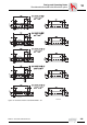
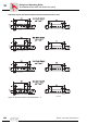
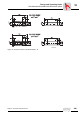
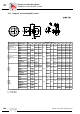
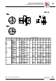
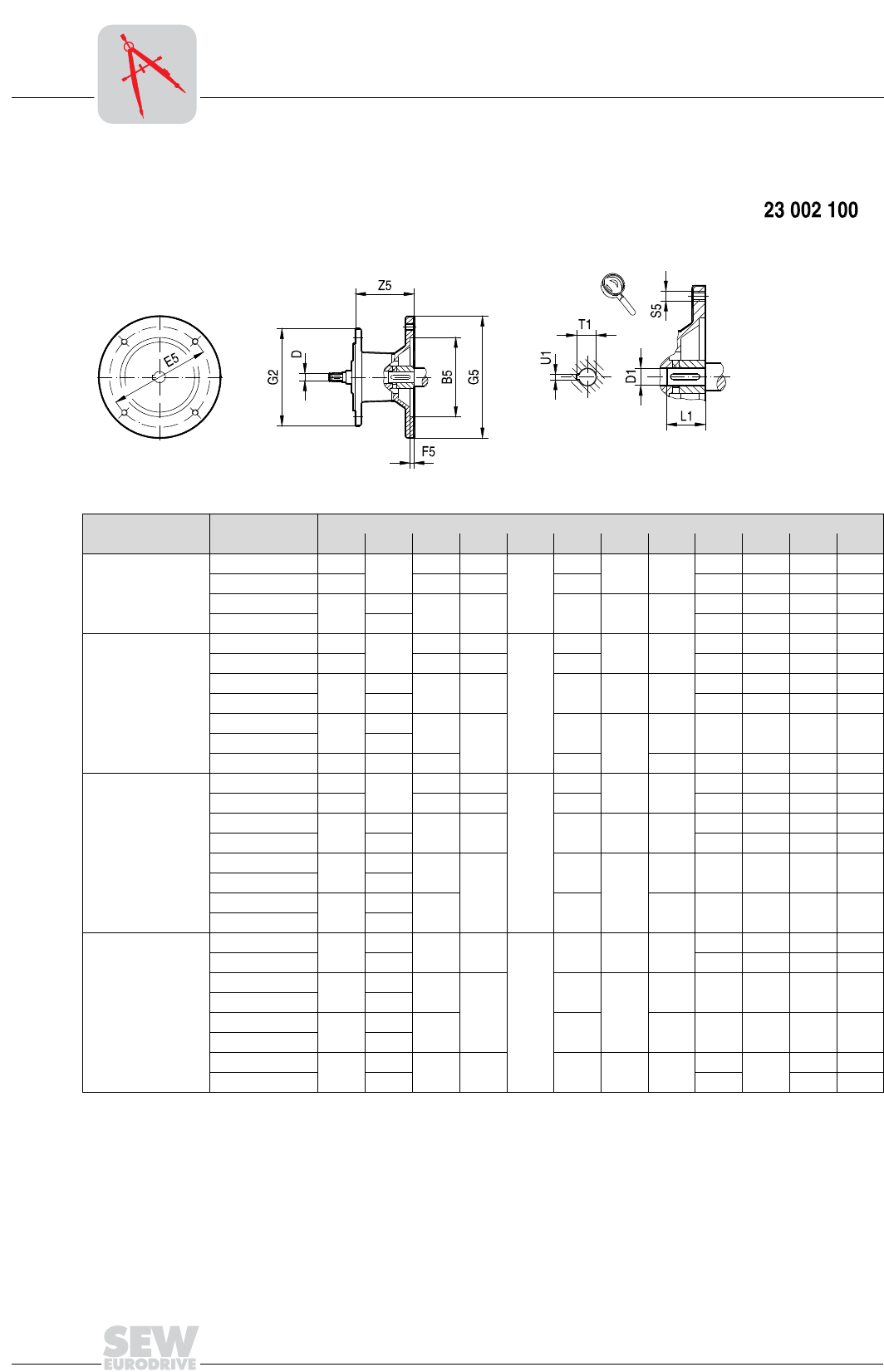
10.6 Adapters for mounting IEC motors
Gear unit type Adapter type
Dimensions in mm
B5 D E5 F5 G2 G5 S5 Z5 D1 L1 T1 U1
R..27, R..37
F..27, F..37, F..47
K..37
S..37, S..47, S..57
AM63 95
10
115 3.5
120
140
M8 72
11 23 12.8 4
AM71
1)
110 130 4 160 14 30 16.3 5
AM80
1)
130
12
165 4.5 200 M10 106
19 40 21.8 6
AM90
1)
14 24 50 27.3 8
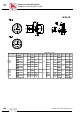
R..47
2)
, R..57, R..67
F..57, F..67
K..47
2)
, K..57, K..67
S..67
AM63 95
10
115 3.5
160
140
M8 66
11 23 12.8 4
AM71 110 130 4 160 14 30 16.3 5
AM80
130
12
1654.5 200M1099
19 40 21.8 6
AM90 14 24 50 27.3 8
AM100
1)
180
16
215
5
250
M12
134 28 60 31.3 8
AM112
1)
18
AM132S/M
1)
230 22 265 300 191 38 80 41.3 10
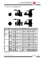
R..77
F..77
K..77
S..77
AM63 95
10
115 3.5
200
140
M8 60
11 23 12.8 4
AM71 110 130 4 160 14 30 16.3 5
AM80
130
12
1654.5 200M1092
19 40 21.8 6
AM90 14 24 50 27.3 8
AM100
1)
180
16
215
5
250
M12
126 28 60 31.3 8
AM112
1)
18
AM132S/M
1)
230
22
265 300 179 38 80 41.3 10
AM132ML
1)
28
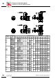
R..87
F..87
K..87
S..87
3)
AM80
130
12
165 4.5
250
200 M10 87
19 40 21.8 6
AM90 14 24 50 27.3 8
AM100
180
16
215
5
250
M12
121 28 60 31.3 8
AM112 18
AM132S/M
230
22
265 300 174 38 80 41.3 10
AM132ML 28
AM160
1)
250
28
300 6 350 M16 232
42
110
45.3 12
AM180
1)
32 48 51.8 14
1) Check dimension 2 G5 because component may protrude past foot-mounting surface if installed on R, K or S foot-mounted gear unit.
2) not with AM112
3) not with AM180