
Technical data
10
194
Manual – Gear Units and Gearmotors
Gear units with hollow shaft
Design and Operating Notes
10.3 Gear units with hollow shaft
Chamfers on
hollow shafts
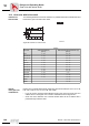
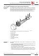
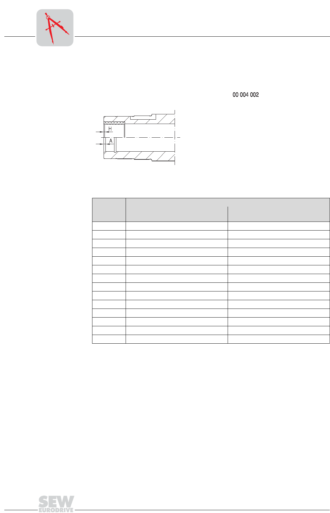
The following illustration shows the chamfers on parallel shaft helical, helical-bevel and
helical-worm gear units with hollow shaft:
Special
motor/gear unit
combinations
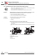
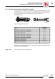
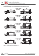
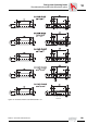
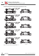
Please note for parallel shaft helical gearmotors with hollow shaft (FA..B, FV..B, FH..B,
FAF, FVF, FHF, FA, FV, FH, FT, FAZ, FVZ, FHZ):
• If you are using a customer shaft pushed through on the motor end, there may be a
collision when a "small gear unit" is used in combination with a "large motor".
• Check the motor dimension AC to decide whether there will be a collision with a
pushed-through customer shaft.
59845AXX
Figure 98: Chamfers on hollow shafts
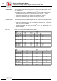
Gear unit
Version
with hollow shaft (A)
[mm x°]
with hollow shaft and shrink disc (H)
[mm x°]
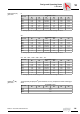
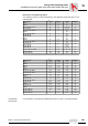
F..27 2 × 30° 0.5 × 45°
F../K../S..37 2 × 30° 0.5 × 45°
F../K../S..47 2 × 30° 0.5 × 45°
S..57 2 × 30° 0.5 × 45°
F../K..57 2 × 30° 0.5 × 45°
F../K../S..67 2 × 30° 0.5 × 45°
F../K../S..77 2 × 30° 0.5 × 45°
F../K../S..87 3 × 30° 0.5 × 45°
F../K../S..97 3 × 30° 0.5 × 45°
F../K..107 3 × 30° 3 × 2°
F../K..127 5 × 30° 1.5 × 30°
F../K..157 5 × 30° 1.5 × 30°
KH167 -1.5 × 30°
KH187 -1.5 × 30°