
Technical data
Manual – Gear Units and Gearmotors
193
10
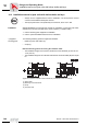
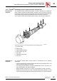
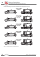
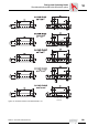
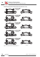
Installation/removal of gear units with hollow shafts and keys
Design and Operating Notes
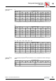
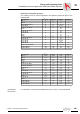
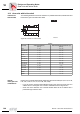
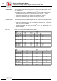
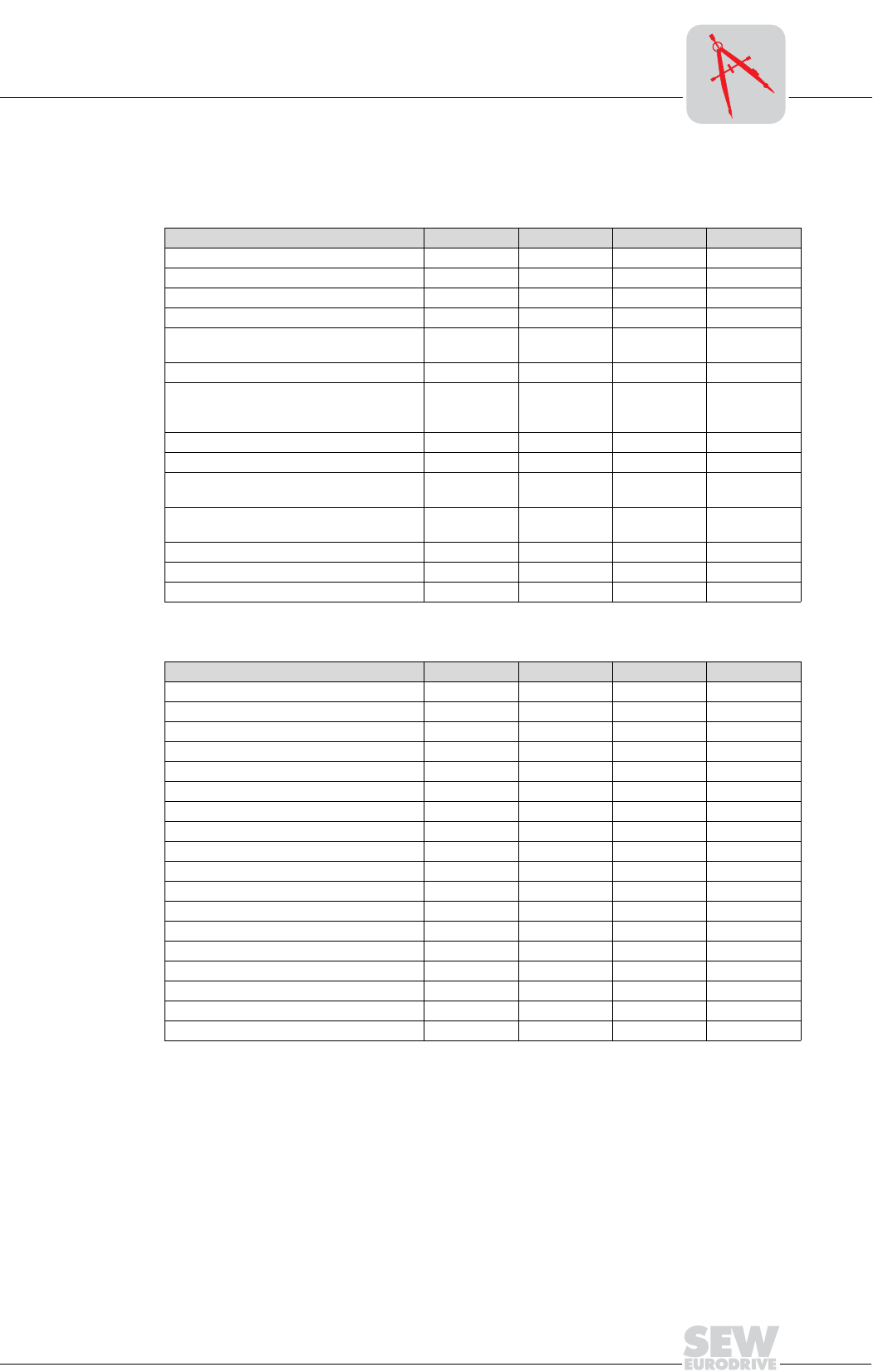
Dimensions and tightening torque:
The retaining screw (2) must be tightened to the tightening torque MS given in the
following table.
2) Installation
/removal tool
For information on the optional installation/removal tool, refer to Tech Note GM-024.
Gear unit type D
H7
[mm] DK [mm] L8 [mm] MS [Nm]
WA..10 16 16 69 8
WA..20 18 18 84 8
WA..20, WA..30, SA..37 20 20 84, 106, 104 8
FA..27, SA..47 25 25 88, 105 20
FA..37, KA..37, SA..47
SA..57
30 30
105
132
20
FA..47, KA..47, SA..57 35 35 132 20
FA..57, KA..57
FA..67, KA..67
SA..67
40 40
142
156
144
40
SA..67 45 45 144 40
FA..77, KA..77, SA..77 50 50 183 40
FA..87, KA..87
SA..77, SA..87
60 60
210
180, 220
80
FA..97, KA..97
SA..87, SA..97
70 70
270
220, 260
80
FA..107, KA..107, SA..97 90 90 313, 313, 255 200
FA..127, KA..127 100 100 373 200
FA..157, KA..157 120 120 460 200
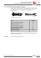
Gear unit type D
H7
[in] DK [in] L8 [in] MS [lb-ft]
WA..10 0.625 0.625 2.72 5.9
WA..20 0.75 0.75 3.31 5.9
WA..30 0.75 0.75 4.17 5.9
SA..37 0.75 0.75 4.09 5.9
FA..27 113.515
FA..37, KA..37, SA.47 1.25 1.25 4.13 15
FA..47, KA..47, SA..57 1.375 1.375 5.2 15
FA..57, KA..57 1.5 1.5 5.59 30
SA..67 1.5 1.5 5.67 30
FA..67, KA..67 1.5 1.5 6.14 30
FA..77, KA..77, SA..77 227.230
FA..87, KA..87 2.375 2.375 8.27 59
SA..87 2.375 2.375 8.66 59
FA..97, KA..97 2.75 2.75 10.63 59
SA..97 2.75 2.75 10.23 59
FA..107, KA..107 3.625 3.625 12.32 148
FA..127, KA..127 4 4 14.69 148
FA..157, KA..157 4.5 4.5 18.11 148