
Technical data
Manual – Gear Units and Gearmotors
155
9
Key to the mounting position sheets
Mounting Positions and Important Order Information
9.3 Key to the mounting position sheets
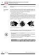
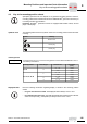
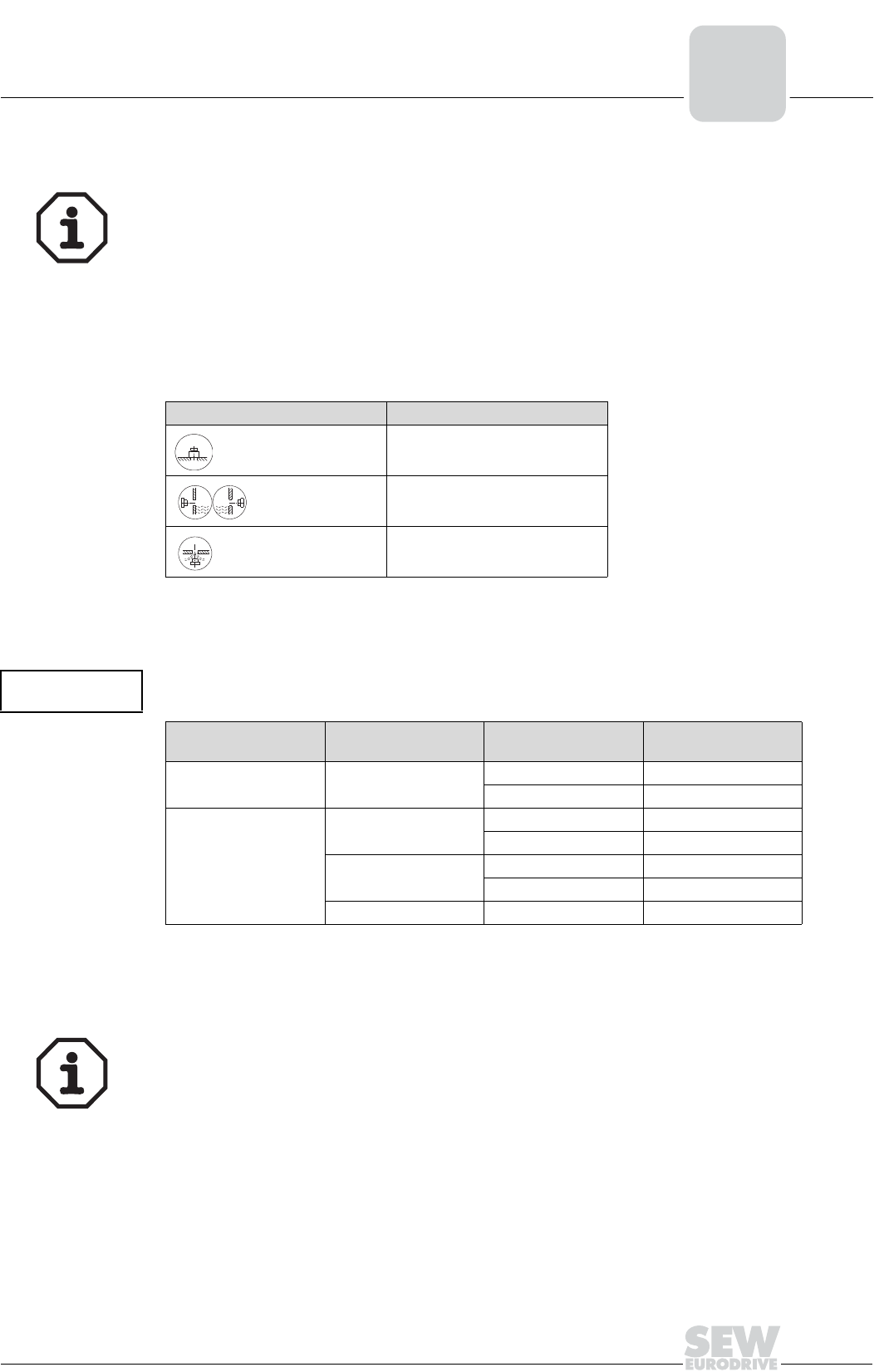
Symbols used The following table shows the symbols used in the mounting position sheets and their
meaning:
Churning losses
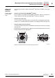
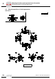
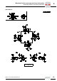
Displayed shaft Note the following information regarding display of shafts in the mounting position
sheets:
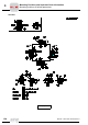
Spiroplan
®
gearmotors do not depend on any particular mounting position. However,
mounting positions M1 to M6 are also shown for SPIROPLAN
®
gearmotors to assist you
in working with this documentation.
Important: Spiroplan
®
gearmotors cannot be equipped with breather valves, oil level
plugs or drain plugs.
Symbol Meaning
Breather valve
Oil level plug
Oil drain plug
* → page 45
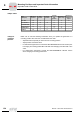
Churning losses may occur in some mounting positions. Contact SEW-EURODRIVE in case of
the following combinations:
Mounting position Gear unit type Gear unit size
Input speed
[1/min]
M2, M4 R
97 ... 107 > 2500
> 107 >1500
M2, M3, M4, M5, M6
F
97 ... 107 > 2500
> 107 > 1500
K
77 ... 107 > 2500
> 107 > 1500
S 77 ... 97 > 2500
• For gear units with solid shaft: The displayed shaft is always on the A end.
• For shaft mounted gear units: The shaft with dashed lines represents the customer
shaft. The output end (Ⳏ shaft position) is always shown on the A end.
M1…M6M1 … M6