
Technical data
8
144
Manual – Gear Units and Gearmotors
Drive properties
Project Planning for AC Motors with Inverter
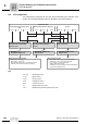
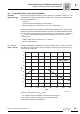
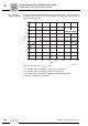
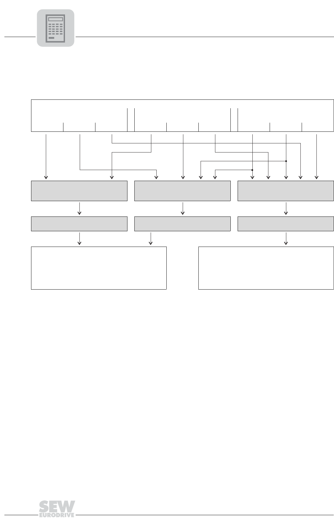
8.2 Drive properties
The required drive properties are the main factors determining the selection of the
inverter. The following illustration serves as assistance for inverter selection.
Key
System selection
Positioning accuracy of the motor
shaft
Setting range (reference 3000 rpm) Control
< ±360° < ±5°...45° < ±1° 1:200 1:800 > 1:800 Pos. reg. n reg. M reg.
U/f without encoder or voltage-con-
trolled flux vector control (VFC)
without encoder.
U/f with encoder or voltage-controlled
flux vector control (VFC) with
encoder.
Current-controlled flux vector control
(CFC) with encoder
– MOVITRAC
®
B
–MOVIDRIVE
®
MDX60/61B
–MOVIDRIVE
®
MDX61B with
DEH11B option
– MOVIDRIVE
®
MDX61B with
DEH11B option
Motor selection for U/f and VFC
– Max. torque < 150 % T
N
– Max. speed < 140 % n
Eck
– Thermal load (setting range, cyclic duration factor)
– Selection of the correct encoder (if necessary)
Motor selection for CFC
– Max. torque < 300 % T
N
for asynchronous servo-
motors and < 180 % Y
N
for AC gearmotors
– R.m.s. torque < T
N
at average speed
– Torque characteristic curves
– Selecting the correct encoder (for example Hiperface
®
encoder only with MCH units)
Pos. reg. = Positioning control
n reg. = Speed control
T reg. = Torque control
VFC = Voltage flux control
CFC = Current flux control
T
N
= Rated torque of the motor
n
trans
= Rated speed (transition speed) of the motor