
Technical data
7
138
Manual – Gear Units and Gearmotors
MOVI-SWITCH® (→ GM)
Project Planning for AC Motors
Available
combinations
The following MOVI-SWITCH
®
AC motors and AC brake motors can be combined with
all suitable gear unit types, mounting positions and versions in accordance with the
selection tables for gearmotors.
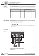
Order information Note the following points when ordering AC (brake) motors or gearmotors with MOVI-
SWITCH
®
:
• Voltage for winding in 댴 connection only.
• Only two brake voltages are possible:
– Motor voltage / √3
or
– motor voltage.
• Position of the terminal box preferably 270°. Please consult SEW-EURODRIVE for
other positions.
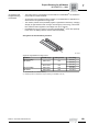
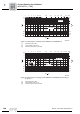
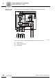
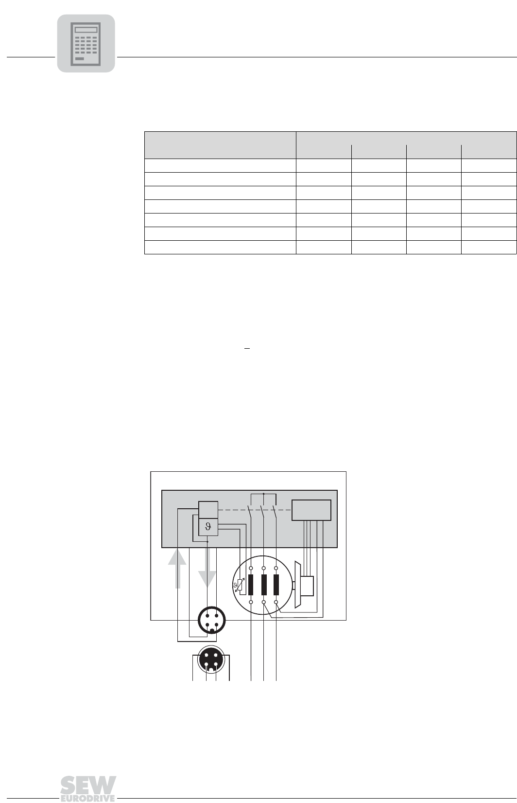
Block diagram
MSW-1E Theory of operation of MOVI-SWITCH
®
MSW-1E:
[1] Brake control
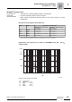
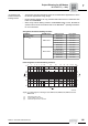
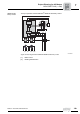
Motor size
Power [HP] with pole number
2 4 6 8
DT71D.. (/BMG)/TF/MSW.. 0.75 0.50 0.33 0.20
DT80K.. (/BMG)/TF/MSW.. 1.0 0.75 0.50 -
DT80N.. (/BMG)/TF/MSW.. 1.5 1.0 0.75 0.33
DT90S.. (/BMG)/TF/MSW.. 2.0 1.5 1.0 0.50
DT90L.. (/BMG)/TF/MSW.. 3.0 2.0 1.5 0.75
DV100M.. (/BMG)/TF/MSW.. 4.0 3.0 2.0 1.0
DV100L.. (/BMG)/TF/MSW.. -4.0-1.5
51946AXX
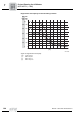
Figure 75: Block diagram MOVI-SWITCH
®
MSW-1E
&
U2 V2
W2
U1 V1
W1
Run
24V
OK
0V
MOVI-SWITCH -1E
®
L1 L2 L3
3
12
4
3
2
1
4
OK
RUN
0V
24V
[1]