
Technical data
7
130
Manual – Gear Units and Gearmotors
MOVIMOT® (→ MM)
Project Planning for AC Motors
Connection technology MOVIMOT
®
standard design
Overview MOVIMOT
®
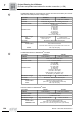
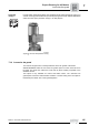
MM..C-503-00 is supplied without plug connector if not specified otherwise
in the order. The plug connectors listed in the following table are preferred components.
For other types, please contact SEW-EURODRIVE.
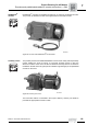
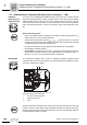
Terminal box design:
The modular terminal box offers the following functions compared to the standard
terminal box:
• The position of the cable entries/plug connectors can later be turned to the opposite
side (see "MOVIMOT
®
" operating instructions).
• Integration of brake control systems (see Sec. "Options")
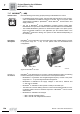
Possible plug
connector
positions
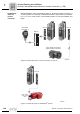
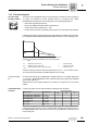
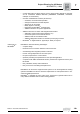
The following positions are possible for plug connectors:
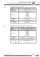
Order designation Function Terminal box
design
Manufacturer designation
MM../AVT1 RS-485 Standard M12 x 1 round plug connector
MM../RE.A/ASA3
RE1A = MM03-15
RE2A = MM22-3X
Power Modular Harting HAN
®
10 ES pin element
(built-on housing with two clips)
MM../RE.A/ASA3/AVT1
RE1A = MM03-15
RE2A = MM22-3X
Power/RS-485 Modular Harting HAN
®
10 ES pin element
(built-on housing with two clips) +
M12 x 1 round plug connector
MM../RE.A/AMA6
RE1A = MM03-15
RE2A = MM22-3X
Power/RS-485 Modular Harting HAN
®
modular pin element
(built-on housing with two clips)
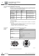
Plug connector Possible positions
AVT1 X (standard)
2
RE.A/ASA3 X (standard)
2
RE.A/ASA3/AVT1 ASA3 = X (standard) + AVT1 = X (standard)
ASA3 = 2 + AVT1 = 2
ASA3 = X + AVT1 = 2
ASA3 = 2 + AVT1 = X
RE.A/AMA6 X (standard)
2
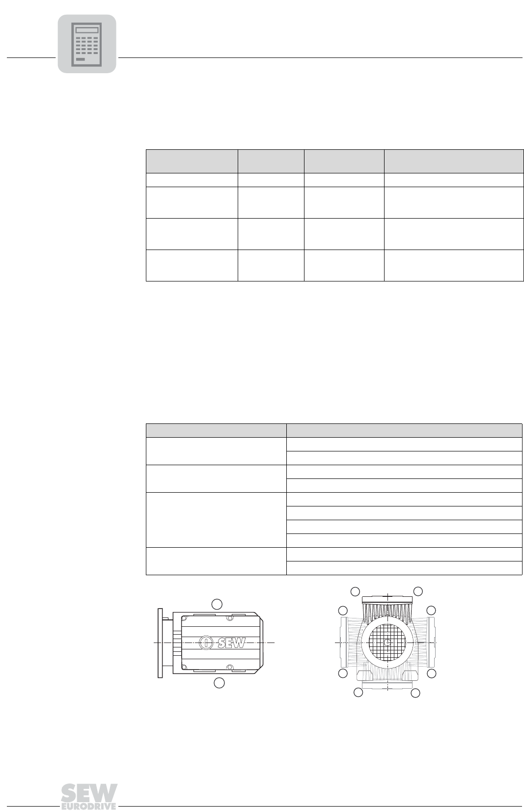
52532AXX
Figure 66: Possible plug connector positions
270˚ (T)
90˚(B)
(R) 0˚
180˚ (L)
2
X
X
2
2
X
2
X
2
X