
Technical data

7
118
Manual – Gear Units and Gearmotors
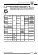
Encoders and prefabricated cables for encoder connection (→ GM)
Project Planning for AC Motors
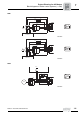
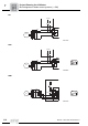
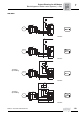
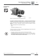
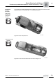
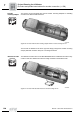
Encoder
connection
When connecting the encoders to the inverters, always follow the operating instructions
for the relevant inverter and the wiring diagrams supplied with the encoders!
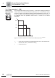
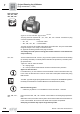
• Maximum line length (inverter – encoder): 100 m (330 ft) with a cable capacitance ≤
120 nF/km
• Conductor cross section: 0.20 ... 0.5 mm
2
(AWG 20 - 24)
• Use shielded cable with twisted pair conductors and apply shield over large area on
both ends :
– At the encoder in the cable gland or in the encoder plug
– To the inverter on the electronics shield clamp or to the housing of the sub D plug
• Install the encoder cables separately from the power cables, maintaining a distance
of at least 200 mm (8 in).
• Encoder with cable gland: Observe the permitted diameter of the encoder cable to
ensure that the cable gland functions correctly.