
Technical data
Manual – Gear Units and Gearmotors
113
7
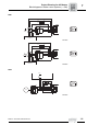
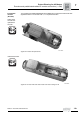
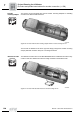
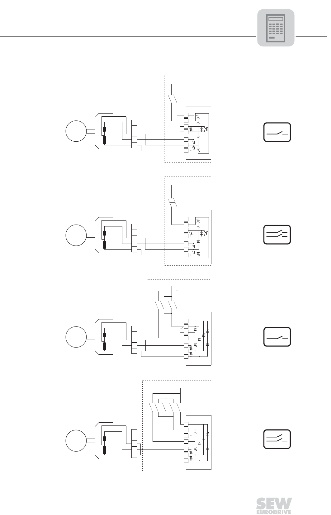
Block diagrams of brake control systems (→ GM)
Project Planning for AC Motors
BMP, BMH
01540BXX
01541BXX
1) Heating
2) Ventilating
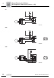
01542BXX
1) Heating
2) Ventilating
01543BXX
4
2
15
RD
WH
TS
BS
B
U
M
BMP
3
13
14
1
3a
4
a
5a
2a
1a
V
AC
AC
4
2
15
RD
WH
TS
BS
BU
M
BMP
3
13
14
1
3a
4a
5a
2a
1a
V
AC
AC
DC
M
BU
BS
TS
WH
RD
15
2
4
1a
2a
5a
4
a
3a
1
14
13
3
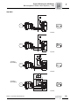
BMH
1)
2)
V
AC
AC
M
BU
BS
TS
WH
RD
15
2
4
1a
2a
5a
4a
3a
1
14
13
3
BMH
V
AC
1)
2)
AC
DC