
Technical data
7
108
Manual – Gear Units and Gearmotors
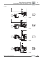
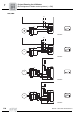
Block diagrams of brake control systems (→ GM)
Project Planning for AC Motors
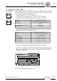
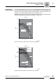
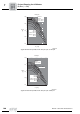
7.11 Block diagrams of brake control systems (→ GM)
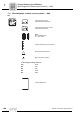
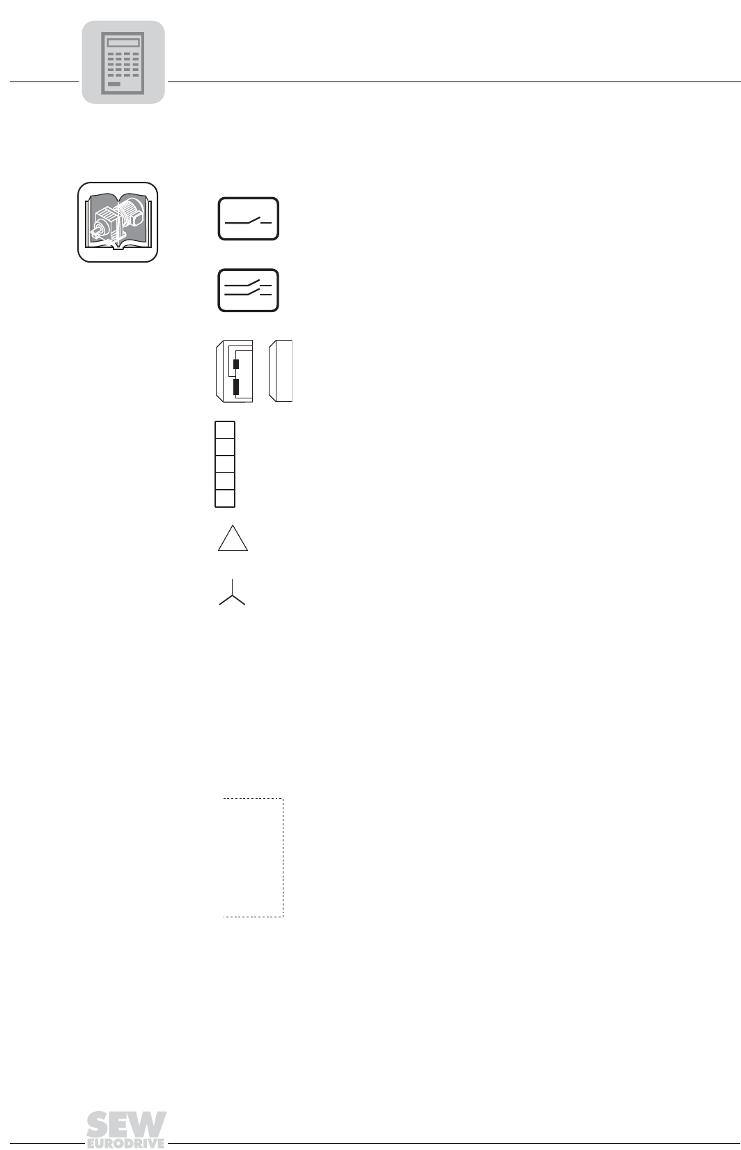
Key
GM
Cut-off in the AC circuit
(standard brake application)
Cut-off in the DC and AC circuits
(rapid brake application)
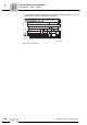
Brake
BS = Accelerator coil
TS = Coil section
Auxiliary terminal strip in terminal box
Motor with delta connection
Motor with star connection
Color coding according to IEC 757:
WH White
RD Red
BU Blue
BN Brown
BK Black
Control cabinet limit
AC
AC
DC
BS
TS
1a
2a
5a
4a
3a