Gearmotors \ Industrial Gear Units \ Drive Electronics \ Drive Automation \ Services Gear Units and Gearmotors 11509031 / US Revision 1 FA100000/US09 Manual
SEW-EURODRIVE – Driving the world
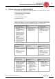
Contents M1 … M6 1 Introduction ....................................................................................................... 6 2 Product Description........................................................................................ 11 3 Unit Designations and Versions .................................................................... 20 4 Project Planning for Drives ............................................................................ 41 5 Project Planning for Gear Units..
Contents 1 2 3 4 5 6 7 8 4 Introduction...................................................................................................................... 6 1.1 The SEW-EURODRIVE Group of Companies ....................................................... 6 1.2 Products and systems from SEW-EURODRIVE .................................................... 7 1.3 Additional documentation ....................................................................................... 9 Product Description .....
Contents 9 10 11 8.4 Torque limit curves with inverter operation......................................................... 147 Mounting Positions and Important Order Information............................................. 149 9.1 General information on mounting positions ........................................................ 149 9.2 Important order information ................................................................................ 150 9.3 Key to the mounting position sheets ..................
Introduction The SEW-EURODRIVE Group of Companies 1 1 Introduction 1.1 The SEW-EURODRIVE Group of Companies Handbuch Global presence Since it introduced the world's first gearmotor 75 years ago, SEW-EURODRIVE has grown to become the global leader in electromechanical and electronic solutions for power transmission and motion control.
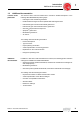
Introduction Products and systems from SEW-EURODRIVE 1.2 1 Products and systems from SEW-EURODRIVE The products and systems from SEW-EURODRIVE are divided into four product groups. These four product groups are: 1. Gearmotors and frequency inverters 2. Servo drive systems 3. Decentralized drive systems 4. Industrial gear units Products and systems used in several group applications are listed in a separate group "Products and systems covering several product groups.
1 Introduction Products and systems from SEW-EURODRIVE 4) Industrial gear units • • • Helical gear units Helical-bevel gear unit Planetary gear units Products and systems for several groups of products • • Operator terminals MOVI-PLC® drive-based control system In addition to its products and systems, SEW-EURODRIVE offers a comprehensive range of services.
Introduction Additional documentation 1.
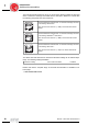
1 Introduction Additional documentation This manual includes references to let you know which catalog includes the technical data / or dimension drawings associated with the description. Reference is made with the following pictograms and cross references: GM MM GK The associated technical data and / or dimension drawings are listed in the catalog "Gearmotors." Also note the cross reference "(→ GM) in the section title and the header.
Product Description General notes on product description 2 Product Description 2.1 General notes on product description Power and torque 2 The power and torque ratings listed in the catalogs refer to mounting position M1 and similar mounting positions in which the input stage is not completely submerged in oil. In addition, the gearmotors are assumed to be standard versions with standard lubrication and under normal ambient conditions.
Product Description General notes on product description 2 Multi-stage gearmotors You can achieve particularly low output speeds by using multi-stage gear units or multistage gearmotors. This involves mounting a helical gear unit or helical gearmotor on the input end as a second gear unit. It may be necessary to limit the motor power to match the maximum permitted output torque of the gear unit.
Product Description General notes on product description Brake motors 2 On request, motors and gearmotors can be supplied with an integrated mechanical brake. The SEW-EURODRIVE brake is an electromagnetic disk brake with a DC coil that releases electrically and brakes using spring force. Due to its operating principle, the brake is applied if the power fails. It meets the basic safety requirements. The brake can also be released mechanically if equipped with a manual brake release.
Product Description Energy efficient motors (→ GM) 2 2.
Product Description Corrosion and surface protection 2.3 2 Corrosion and surface protection General information Corrosion protection KS SEW-EURODRIVE offers various optional protective measures for operation of motors and gear units in excessive conditions. • Corrosion protection KS for motors • Industry option package Corrosion protection KS for motors comprises the following measures: • Stainless steel retaining screws.
Product Description Corrosion and surface protection 2 Surface protection OS Instead of the standard surface protection, the motors and gear units are available with surface protection OS1 to OS4 as an option. The special procedure Z can also be performed in addition. The special procedure Z means that large surface recesses are sprayed with a rubber filling prior to painting.
Product Description Extended storage 2.4 2 Extended storage Type You can also order the gear units prepared for "extended storage". SEW-EURODRIVE recommends the "extended storage" type for storage periods longer than 9 months. In this case, a VCI (volatile corrosion inhibitor) is added to the lubricant in these gear units. Please note that this VCI corrosion inhibitor is only effective in a temperature range of -25 °C...+50 °C.
Product Description Drives for applications in hygienic areas 2 2.5 Drives for applications in hygienic areas High demands are placed on hygiene both for the production of beverages and food and in the chemical and pharmaceutical industries. Often, regulations stipulate a completely germ-free environment. The drive solutions used in the past made it very hard to clean the production system as thoroughly as required. Standard motors usually have cooling fins and fans.
Product Description Drives for applications in hygienic areas Drive package ASEPTICplus 2 The ASEPTICplus drive package combines the following additional measures and specific components for the gearmotor in hygienic design for the best possible protection for the gearmotor against cleaning agents, chemicals and aggressive environmental conditions.
Unit Designations and Versions Unit designations for gear units and options 3 3 Unit Designations and Versions 3.1 Unit designations for gear units and options Helical gear units RX.. Single-stage foot mounted version RXF.. Single-stage B5 flange-mounted version R.. Foot-mounted version R..F Foot-mounted and B5 flange-mounted version RF.. B5 flange-mounted version RZ.. B14 flange-mounted version RM..
Unit Designations and Versions Unit designations for gear units and options KH.. Hollow shaft with shrink disc KT.. Hollow shaft with TorqLOC® hollow shaft mounting system KT..B Foot-mounted hollow shaft with TorqLOC® hollow shaft mounting system KV.. Hollow shaft with splined hollow shaft to DIN 5480 KAZ.. B14 flange-mounted version and hollow shaft KHZ.. B14 flange-mounted and hollow shaft with shrink disc KVZ..
Unit Designations and Versions Unit designations for components on the input side 3 3.2 Unit designations for components on the input side Adapter Adapter for mounting IEC/NEMA motors AM.. ../RS ..and backstop Adapter for mounting servomotors AQ.. AQA with keyway AQH with clamping ring hub Adapter with torque limiting coupling AR.. ../W ..and speed monitoring ../WS ..and slip monitoring Adapter with hydraulic centrifugal coupling AT .. ../RS ..and backstop ../BM(G) ..and disc brake ..
Unit Designations and Versions Example for the unit designation of a gear unit 3.4 3 Example for the unit designation of a gear unit The unit designation of the gear unit starts from the component on the output end.
Unit Designations and Versions Unit designations for AC motors and options 3 3.5 Unit designations for AC motors and options Standard AC motor of the series DT.., DV.. Foot-mounted version DR.., ..DT.., ..DV.. Attached motor for gear units DFR.., DFT.., DFV.. Flange-mounted version DT..F, DV..F Foot and flange-mounted version Multi-speed AC motors with soft start SDT.., SDV.. Foot-mounted version SDFT.., SDFV.. Flange-mounted version SDT..F, SDV..
Unit Designations and Versions Unit designations for AC motors and options 3 Plug connector on AC motor options /IS Integrated plug connector /AMA.. HAN modular 10B plug connector on terminal box with two-clamp closure /AMB.. HAN modular 10B plug connector on terminal box with two-clamp closure and EMC housing /ASA.. HAN modular 10ES plug connector on terminal box with two-clamp closure /ASB.. HAN modular 10ES plug connector on terminal box with two-clamp closure and EMC housing /ACA..
Unit Designations and Versions Example for the unit designation of a gearmotor 3 3.6 Example for the unit designation of a gearmotor The unit designation of the gearmotor starts from the component on the output end.
Unit Designations and Versions Examples for the unit designation of AC (brake) motors 3.
Unit Designations and Versions Unit designations MOVIMOT® standard design 3 Unit designations MOVIMOT® standard design 3.8 Mechanical versions DT.. MM.., DV.. MM.. Foot-mounted version ..DT.. MM.., ..DV.. MM.. Attached motor for gear units DFT.. MM.., DFV.. MM.. Flange-mounted version DT..F MM.., DV..F MM.. Foot and flange-mounted version Plug connector /AVT1 M12 plug connector for RS-485 connection /RE.A/ASA3 HAN® 10ES plug connector with two-clip closure for power /RE.
Unit Designations and Versions Unit designations for MOVIMOT® with integrated AS-interface 3 Unit designations for MOVIMOT® with integrated AS-interface 3.9 Mechanical versions DT.. MM.., DV.. MM.. Foot-mounted version ..DT.. MM.., ..DV.. MM.. Attached motor for gear units DFT.. MM.., DFV.. MM.. Flange-mounted version DT..F MM.., DV..F MM..
Unit Designations and Versions Example for the unit designation of a MOVIMOT® gearmotor 3 3.10 Example for the unit designation of a MOVIMOT® gearmotor The unit designation of the MOVIMOT® gearmotor starts from the component on the output end.
Unit Designations and Versions Gearmotor types 3.11 3 Gearmotor types The types described in this section refer to gearmotors from SEW-EURODRIVE. They also apply to gear units without motor (without DR/DT/DV) and for MOVIMOT® gearmotors (../MM..). Helical gearmotors The following types of helical gearmotors can be supplied: RX..DR/DT/DV.. Single-stage foot-mounted helical gearmotor RXF..DR/DT/DV.. Single-stage B5 flange-mounted helical gearmotor R..DR/DT/DV.. Foot-mounted helical gearmotor R..
Unit Designations and Versions Gearmotor types 3 Parallel shaft helical gearmotors The following types of parallel shaft helical gearmotors can be supplied: F..DR/DT/DV.. Foot-mounted parallel shaft helical gearmotor FA..B DR/DT/DV.. Foot-mounted parallel shaft helical gearmotor with hollow shaft FV..B DR/DT/DV.. Foot-mounted parallel shaft helical gearmotor with hollow shaft and splined hollow shaft to DIN 5480 FH..B DR/DT/DV..
Unit Designations and Versions Gearmotor types 3 FHF..DR/DT/DV.. Parallel shaft helical gearmotor in B5 flange-mounted version with hollow shaft and shrink disc FA..DR/DT/DV.. Parallel shaft helical gearmotor with hollow shaft FV..DR/DT/DV.. Parallel shaft helical gearmotor with hollow shaft and splined hollow shaft to DIN 5480 FH..DR/DT/DV.. Parallel shaft helical gearmotor with hollow shaft and shrink disc FT..
Unit Designations and Versions Gearmotor types 3 Helical-bevel gearmotors The following types of helical-bevel gearmotors can be supplied: K..DR/DT/DV.. Foot-mounted helical-bevel gearmotor KA..B DR/DT/DV.. Foot-mounted helical-bevel gearmotor with hollow shaft KV..B DR/DT/DV.. Foot-mounted helical-bevel gearmotor with hollow shaft and splined hollow shaft to DIN 5480 KH..B DR/DT/DV.. Foot-mounted helical-bevel gearmotor with hollow shaft and shrink disc KF..DR/DT/DV..
Unit Designations and Versions Gearmotor types 3 KHF..DR/DT/DV.. Helical-bevel gearmotor in B5 flange-mounted version with hollow shaft and shrink disc KA..DR/DT/DV.. Helical-bevel gearmotor with hollow shaft KV..DR/DT/DV.. Helical-bevel gearmotor with hollow shaft and splined hollow shaft to DIN 5480 KH..DR/DT/DV.. Helical-bevel gearmotor with hollow shaft and shrink disc KT..DR/DT/DV.. Helical-bevel gearmotor with hollow shaft and TorqLOC® hollow shaft mounting system KAZ..DR/DT/DV..
Unit Designations and Versions Gearmotor types 3 Helical-worm gearmotors The following types of helical-worm gearmotors can be supplied: S..DR/DT/DV.. Foot-mounted helical-worm gearmotor SF..DR/DT/DV.. Helical-worm gearmotor in B5 flange-mounted version SAF..DR/DT/DV.. Helical-worm gearmotor in B5 flange-mounted version with hollow shaft SHF..DR/DT/DV..
Unit Designations and Versions Gearmotor types 3 SA..DR/DT/DV.. Helical-worm gearmotor with hollow shaft SH..DR/DT/DV.. Helical-worm gearmotor with hollow shaft and shrink disc ST..DR/DT/DV.. Helical-worm gearmotor with hollow shaft and TorqLOC® hollow shaft mounting system SAZ..DR/DT/DV.. Helical-worm gearmotor in B14 flange-mounted version with hollow shaft SHZ..DR/DT/DV..
Unit Designations and Versions Gearmotor types 3 Spiroplan® gearmotors The following types of Spiroplan® gearmotors can be supplied: W..DR/DT.. Spiroplan® gearmotor in foot-mounted version WF..DR/DT.. Spiroplan® gearmotor in flange-mounted version WA..DR/DT.. Spiroplan® gearmotor with hollow shaft WAF..DR/DT..
Unit Designations and Versions Types of components on the input side 3.
Unit Designations and Versions Types of AC (brake) motors (→ GM) 3 3.13 Types of AC (brake) motors (→ GM) The following figure shows an example of components of AC (brake) motors: GM DT, DV../BM(G) DFT, DFV../MSW DFT, DFV../ASB8 DFT, DFV../MM DFR../BR/IS, DFT, DFV..
Project Planning for Drives Additional documentation 4 Project Planning for Drives 4.1 Additional documentation 4 In addition to the information in this manual, SEW-EURODRIVE offers extensive documentation covering the entire topic of electrical drive engineering. These are mainly the publications in the "Drive Engineering – Practical Implementation" series as well as the manuals and catalogs for electronically controlled drives.
Project Planning for Drives Drive selection data 4 4.2 Drive selection data Certain data is essential to specify the components for your drive precisely.
Project Planning for Drives Project planning sequence 4.3 4 Project planning sequence Example The following flow diagram illustrates the project planning procedure for a positioning drive. The drive consists of a gearmotor that is powered by an inverter.
Project Planning for Gear Units Efficiency of gear units 5 5 Project Planning for Gear Units 5.1 Efficiency of gear units General information The efficiency of gear units is mainly determined by the gearing and bearing friction. Keep in mind that the starting efficiency of a gear unit is always less than its efficiency at operating speed. This factor is especially pronounced in the case of helical-worm and Spiroplan® right-angle gearmotors.
Project Planning for Gear Units Efficiency of gear units Run-in phase 5 The tooth flanks of new helical-worm and Spiroplan® gear units are not yet completely smooth. That fact makes for a greater friction angle and less efficiency than during later operation. This effect intensifies with increasing gear unit ratio. Subtract the following values from the listed efficiency during the run-in phase: Spiroplan® Worm i range η reduction i range η reduction 1 start approx. 50 ... 280 approx.
Project Planning for Gear Units Oil compensator 5 5.2 Oil compensator The oil compensator allows the lubricant/air space of the gear unit to expand. This means no lubricant can escape the breather valve at high operating temperatures. SEW-EURODRIVE recommends to use oil compensators for gear units and gearmotors in M4 mounting position and for input speeds > 2000 rpm. b c a 59648AXX Figure 7: Oil compensator Gear unit Motor Package no. Dimension a [in] Dimension b [in] Dimension c [in] R27 ...
Project Planning for Gear Units Multi-stage gearmotors (→ GM) 5.3 5 Multi-stage gearmotors (→ GM) General information GM Limiting the motor power You can achieve particularly low output speeds by using multi-stage gear units or multistage gearmotors. This means an additional second gear unit, usually a helical gear unit, is installed in front of the gear unit or between gear unit and motor. The resulting total reduction ratio may make it necessary to protect the gear units.
Project Planning for Gear Units Service factor 5 5.4 Service factor Determining the service factor The effect of the driven machine on the gear unit is taken into account to a sufficient level of accuracy using the service factor fB. The service factor is determined according to the daily operating time and the starting frequency Z. Three load classifications are taken into account depending on the mass acceleration factor. You can read off the service factor applicable to your application in Figure 8 .
Project Planning for Gear Units Service factor Mass acceleration factor 5 The mass acceleration factor is calculated as follows: Mass acceleration factor = All external mass moments of inertia Mass moment of inertia on the motor end "All external mass moments of inertia" are the mass moments of inertia of the driven machine and the gear unit, scaled down to the motor speed.
Project Planning for Gear Units Service factor 5 Helical-worm gear units For helical-worm gear units, two additional service factors will have to be taken into consideration besides service factor fB derived from Figure 8 . These are: • fB1 = Service factor from ambient temperature • fB2 = Service factor from cyclic duration factor The additional service factors fB1 and fB2 can be determined by referring to the diagrams in Figure 9 .
Project Planning for Gear Units Overhung and axial loads (→ GM, → MM, → GK) 5.5 5 Overhung and axial loads (→ GM, → MM, → GK) Determining overhung load An important factor for determining the resulting overhung load is the type of transmission element mounted to the shaft end. The following transmission element factors fZ have to be considered for various transmission elements. Transmission element GM MM Transmission element factor fZ Comments Gears 1.15 < 17 teeth Chain sprockets 1.
Project Planning for Gear Units Overhung and axial loads (→ GM, → MM, → GK) 5 Higher permitted overhung loads Exactly considering the force application angle α and the direction of rotation makes it possible to achieve a higher overhung load. Higher output shaft loads are permitted if heavy duty bearings are installed, especially with R, F and K gear units. Contact SEWEURODRIVE in such cases.
Project Planning for Gear Units Overhung and axial loads (→ GM, → MM, → GK) On the input side: Overhung load conversion for off-center force application Important: only applies to gear units with input shaft assembly: On the output side: Overhung load conversion for off-center force application The permitted overhung loads must be calculated according the selection tables using the following formulae in the event that force is not applied at the center of the shaft end.
Project Planning for Gear Units Overhung and axial loads (→ GM, → MM, → GK) 5 Gear unit constants for overhung load conversion Gear unit type a [in] b [in] c [lb-in] f [in] d [in] l [in] RX57 RX67 RX77 RX87 RX97 RX107 1.71 2.07 2.38 2.89 3.41 4.04 0.93 1.08 1.20 1.32 1.44 1.67 1.34 2.14 1.73 6.81 12.66 21.86 1.35 1.56 0 1.93 2.12 2.45 0.750 1.000 1.250 1.625 2.125 2.375 1.57 1.97 2.36 3.15 3.94 4.72 R07 R17 R27 R37 R47 R57 R67 R77 R87 R97 R107 R137 R147 R167 2.83 3.48 4.19 4.65 5.39 5.
Project Planning for Gear Units RM gear units 5.6 5 RM gear units Project planning You must take into account the higher overhung loads and axial forces when planning projects using RM helical gearmotors with extended bearing housing.
Project Planning for Gear Units RM gear units 5 Permitted overhung loads and axial forces The permitted overhung loads FRa and axial forces FAa are specified for various service factors fB and nominal bearing service life L10h. fBmin = 1.
Project Planning for Gear Units RM gear units Conversion factors and gear unit constants Additional weight RM gear units 5 The following conversion factors and gear unit constants apply to calculating the permitted overhung load FxL at point x ≠ 1000 mm for RM gearmotors: Gear unit type a b cF (fB = 1.5) cF (fB = 2.0) FF RM57 1047 47 1220600 1260400 277 RM67 1047 47 2047600 2100000 297.5 RM77 1050 50 2512800 2574700 340.5 RM87 1056.5 56.
Project Planning for Gear Units Drives for overhead trolley systems 5 5.7 Drives for overhead trolley systems Special gearmotors with integrated coupling are required for operating overhead trolley systems. SEW-EURODRIVE offers a range of drives for overhead trolley systems. You will find detailed information on this topic in the "Drives for Overhead Trolley Systems" catalog.
Project Planning for Components on the Input Side Gear units with IEC or NEMA adapter AM (→ GK) 6 Project Planning for Components on the Input Side 6.1 Gear units with IEC or NEMA adapter AM (→ GK) 6 GK 04588AXX Figure 14: Helical-worm gear unit with adapter AM For mounting motors according to IEC standard or NEMA (type C or TC) to SEW helical gear units, parallel shaft helical gear units, helical-bevel and helical-worm gear units. Adapters are available for sizes 63 to 280 for IEC motors.
Project Planning for Components on the Input Side Gear units with IEC or NEMA adapter AM (→ GK) 6 Power ratings, mass moments of inertia Type (IEC) Type (NEMA) Pm1) [HP] Jadapter [lb-ft²] AM63 - 0.33 10.45 • 10-4 AM71 AM56 0.50 10.45 • 10-4 AM80 AM143 1.0 45.125 • 10-4 AM90 AM145 2.0 45.125 • 10-4 AM100 AM182 4 123.5 • 10-4 AM112 AM184 5.4 123.5 • 10-4 AM132S/M AM213/215 10 451.25 • 10-4 AM132ML - 12.5 451.25 • 10-4 AM160 AM254/256 20 2161.
Project Planning for Components on the Input Side Gear units with IEC or NEMA adapter AM (→ GK) Backstop AM../RS 6 If the application requires only one direction of rotation, the AM adapter can be configured with a backstop. Backstops with centrifugal lift-off sprags are used. The advantage of this design is that the sprags move around inside the backstop without making contact above a certain speed (lift-off speed).
Project Planning for Components on the Input Side Adapter AQ for servomotors (→ GK) 6 6.2 Adapter AQ for servomotors (→ GK) GK 04595AXX Figure 16: Helical gear unit with AQ adapter An adapter with square flange is used for mounting servomotors onto SEW helical, parallel shaft helical, helical-bevel and helical-worm gear units. The torque is transmitted via a elastomeric spider.
Project Planning for Components on the Input Side Adapter AQ for servomotors (→ GK) Torques, mass moments of inertia Type AQ..80/.. AQ..100/.. AQ..115/1 AQ..115/2 AQ..115/3 AQ..140/1 AQ..140/2 AQ..140/3 AQ..190/1 AQ..190/2 AQ..190/3 dRZ1) [mm] Te max2) [lb-in] 10 68 12 115 10 68 12 115 14 133 16 133 10 68 12 115 14 168 16 265 16 265 18 365 22 470 16 265 18 365 22 665 22 665 28 1280 22 665 28 1500 6 Jadapter3) [lb-ft2] 21.375 • 10-4 38.10-4 87.
Project Planning for Components on the Input Side Adapter AQ for servomotors (→ GK) 6 Selecting the gear unit Determine the gear unit type ↓ Determine the gear unit size by means of the • Maximum output torque (Ta max) • Gear ratio (i) in the selection tables AQ ↓ Check the maximum permitted overhung load value on the output (FRa) ↓ Check the permitted input torques on the gear unit (Te max) (see “Power ratings, mass moments of intertia" on the previous page) ↓ Is the required adapter size available? ↓ I
Project Planning for Components on the Input Side Adapter AR with torque limiting coupling (→ GK) 6.3 6 Adapter AR with torque limiting coupling (→ GK) GK 04604AXX Figure 17: Helical-bevel gear unit with AR adapter SEW helical, parallel shaft helical, helical-bevel and helical-worm gear units are designed with adapter and torque limiting coupling to protect the machine and the drive against overload. IEC standard motors of sizes 71 to 180 can be mounted.
Project Planning for Components on the Input Side Adapter AR with torque limiting coupling (→ GK) 6 Torques, slip torques Type Pm1) [HP] TR2) [lb-in] TR2) [lb-in] TR2) [lb-in] AR71 0.5 8.9 - 53 54 - 142 - AR80 1.0 8.9 - 53 54 - 142 - AR90 2.0 8.9 - 53 54 - 142 150 - 285 AR100 4.0 44 - 115 124 - 710 - AR112 5.4 44 - 115 124 - 710 - AR132S/M 10.0 133 - 1150 - - AR132ML 12.5 133 - 1150 - - AR160 20.0 265 - 750 760 - 1770 - AR180 30.
Project Planning for Components on the Input Side Adapter AR with torque limiting coupling (→ GK) Slip monitor /WS option 6 In conjunction with Varigear® variable speed gear units (see Variable Speed Gear Units catalog), the speed monitor is replaced by a slip monitor for monitoring the speed difference between the input and output halves of the coupling. The signal pick-up depends on the size of the variable speed gear unit and consists of two encoders or one encoder and an AC tachogenerator.
6 Project Planning for Components on the Input Side Adapter AR with torque limiting coupling (→ GK) Terminal assignment W [7] [6] /W [4] 1 9 2 10 3 11 4 12 5 13 6 14 7 15 8 16 [1] [2] 53653AXX Figure 20: Terminal assignment /W [1] [2] [3] [4] [5] Relay output Supply voltage AC 110 V (50...
Project Planning for Components on the Input Side Adapter AR with torque limiting coupling (→ GK) 6 Dimensions W 52250AXX Figure 22: Dimensions /W in mm Dimensions WS 45 120 3 4 5 6 7 8 9 10 11 12 35.
Project Planning for Components on the Input Side Adapter with hydraulic centrifugal coupling AT (→ GK) 6 6.4 Adapter with hydraulic centrifugal coupling AT (→ GK) GK 04607AXX Figure 24: Parallel shaft helical gear unit with adapter AT SEW helical, parallel shaft helical, helical-bevel and helical-worm gear units can be combined with adapters and hydraulic centrifugal couplings for machines with high inertia starting (e.g. mixers, agitators, etc.).
Project Planning for Components on the Input Side Adapter with hydraulic centrifugal coupling AT (→ GK) Centrifugal coupling 6 The centrifugal coupling used is a hydrodynamic coupling that operates according to the Föttinger principle. The coupling is filled with oil and consists of a pump wheel (motor side) and a turbine wheel (gear unit side). The pump wheel converts the input mechanical energy into fluid energy and the turbine wheel converts this energy back into mechanical energy.
Project Planning for Components on the Input Side Adapter with hydraulic centrifugal coupling AT (→ GK) 6 Characteristic curves Motor startup Driven machine startup T/T N T/T N 2 2 Torque /time characteristic TM T/T N 2 TK TK TM 1 1 1 0 0 TL TK 0 5 sec. Motor speed TM Motor torque TL Load torque Selecting the gear unit Machine speed 20 sec.
Project Planning for Components on the Input Side Adapter with hydraulic centrifugal coupling AT (→ GK) 6 Backstop AT../RS option If the application requires only one permitted direction of rotation, the hydraulic centrifugal coupling can be configured with a backstop. Backstops with centrifugal lift-off sprags are used. The advantage of this design is that the sprags move around in the backstop without making contact above a certain speed.
Project Planning for Components on the Input Side Adapter with hydraulic centrifugal coupling AT (→ GK) 6 Disc brake AT../BM(G) option 04611AXX Figure 27: Parallel shaft helical gear unit with adapter AT and disc brake BM(G) The adapter with hydraulic centrifugal coupling can be configured with an SEW disc brake if the machine is to be braked in a defined manner. The brake is an electromagnetic disc brake with a DC coil which is released electrically and braked using spring force.
Project Planning for Components on the Input Side Project planning for helical-bevel gear units on swing base MK (→ GK) 6.5 6 Project planning for helical-bevel gear units on swing base MK (→ GK) GK 04616AXX Figure 28: Helical-bevel gear unit on swing base MK Pre-assembled drive units comprising helical bevel gear units, hydraulic centrifugal couplings and electric motors are available especially for conveyor systems, bucket conveyors and other machines with high inertia starting.
Project Planning for Components on the Input Side Project planning for helical-bevel gear units on swing base MK (→ GK) 6 Structure [1] [2] [3] [4] [5] [6] [7] [8] [9] 52255AXX Figure 29: Helical-bevel gear unit on swing base MK [1] [2] [3] [4] [5] 76 Helical-bevel gear unit Mounting rail Oil pan Protective canopy Hydraulic centrifugal coupling [6] [7] [8] [9] Thermal monitoring device (optional design) Electric motor Torque arm (optional design) Speed monitor (optional design, only in conju
Project Planning for Components on the Input Side Project planning for helical-bevel gear units on swing base MK (→ GK) Centrifugal coupling 6 The centrifugal coupling used is a hydrodynamic coupling that operates according to the Föttinger principle. The coupling is filled with oil and consists of a pump wheel (motor side) and a turbine wheel (gear unit side). The pump wheel converts the input mechanical energy into fluid energy and the turbine wheel converts this energy back into mechanical energy.
Project Planning for Components on the Input Side Project planning for helical-bevel gear units on swing base MK (→ GK) 6 Mechanical thermal monitoring device /MTS Using a mechanical thermal monitoring device can prevent the operating fluid from being sprayed into the environment. A switch pin screwed into the coupling releases a spring-loaded switch pin if the temperature reaches an excessive level.
Project Planning for Components on the Input Side Input shaft assembly AD (→ GK) 6.6 6 Input shaft assembly AD (→ GK) GK 04583AXX Figure 33: Helical gear unit with AD input shaft assembly SEW helical, parallel shaft helical, helical-bevel and helical-worm gear units are equipped with an input shaft assembly for drive via an exposed shaft extension. The dimensions of the drive shafts are given in metric units according to IEC standard (dimensions in inch on request).
Project Planning for Components on the Input Side Input shaft assembly AD (→ GK) 6 Selecting the gear unit Determine the gear unit type ↓ Determine the gear unit size by means of the • Maximum output torque (Ta max) • Gear ratio (i) in the gear unit selection tables with input shaft assembly AD When selecting AD/P, please observe the selection note on page 82. ↓ Check the maximum permitted overhung load value on the output (FRa).
Project Planning for Components on the Input Side Input shaft assembly AD (→ GK) 6 Centering shoulder AD../ZR The input shaft assembly can be configured with a centering shoulder as an option. In this way, a customer’s application can be attached to the cover centrally in relation to the input shaft side. Backstop AD../RS The input shaft assembly can be supplied with a backstop if the application only requires one permitted direction of rotation. Backstops with centrifugal lift-off sprags are used.
Project Planning for Components on the Input Side Input shaft assembly AD (→ GK) 6 Motor mounting platform AD.. /P Belt drives are available with adjustable motor mounting platform for space-saving installation. The motor mounting platform is arranged parallel to the drive shaft and is without tapped holes (also available with tapped holes for IEC standard on request). The distance from the input shaft can be adjusted using threaded columns.
Project Planning for Components on the Input Side Input shaft assembly AD (→ GK) Thermal limit power for gear units with input shaft assembly 6 The power values given in the selection tables for gear units with input shaft assemblies are mechanical limit powers. Depending on the mounting position, however, gear units may become thermally overloaded before they reach the mechanical power limit.
Project Planning for AC Motors Possible motor options (→ GM, → MM) 7 7 Project Planning for AC Motors 7.1 Possible motor options (→ GM, → MM) Overview GM MM Technical data and dimension drawings The following motor options are available in various combinations: • BM(G)/BR disc brakes (→ page 103) • IS integrated plug connector (→ page 115) • Plug connectors AS.., AC.., AM.., AB.., AD.., AK..
Project Planning for AC Motors Standards and regulations (→ GM) 7.2 7 Standards and regulations (→ GM) Conformance to standards AC motors and AC brake motors from SEW-EURODRIVE conform to the relevant standards and regulations, in particular: • IEC 60034-1, EN 60034-1 Rotating electrical machinery, rating and performance. • EN 60529 IP degrees of protection provided by enclosures of electrical equipment. • IEC 60072 Dimensions and performance of rotating electrical machinery.
Project Planning for AC Motors Standards and regulations (→ GM) 7 Tolerances According to IEC 60034 (EN 60034), the following tolerances are permitted for electric motors (also applies to the rated voltage range): Voltage and frequency Tolerance A or tolerance B PN ≤ 67 HP PN > 67 HP Efficiency η Power factor cosϕ PN < 1.3 HP PN ≥ 1.3 HP Slip Tolerance A, tolerance B -0.15 • (1-η) -0.1 • (1-η) 1 - cosϕ 6 ±30% ±20% Starting current +20% Tightening torque -15%...
Project Planning for AC Motors Circuit breakers and protective equipment 7.3 7 Circuit breakers and protective equipment EMC measures AC motors, AC brake motors and MOVIMOT® drives from SEW-EURODRIVE are components for installation in machinery and systems. The designer of the machine or system is responsible for complying with the EMC Directive 89/336/EEC.
Project Planning for AC Motors Circuit breakers and protective equipment 7 Motor protection Selecting the correct protection device is a significant factor in determining the operational reliability of the motor. We distinguish between protection devices that are currentdependent and those that depend on the motor temperature. Current-dependent protection devices include fuses or motor circuit breakers.
Project Planning for AC Motors Circuit breakers and protective equipment Secure switching of inductances 7 Note the following notes for switching of inductances: • Switching of low-speed motor windings. If the cable is installed unfavorably, switching of low-speed motor windings can generate voltage peaks. Voltage peaks can damage windings and contacts. Install varistors in the incoming cable to avoid such problems. • Switching of brake coils.
Project Planning for AC Motors Electrical characteristics (→ GM, → MM) 7 7.4 Electrical characteristics (→ GM, → MM) Suitability for use with an inverter AC (brake) motors can be operated on inverters, for example SEW-EURODRIVE MOVIDRIVE®, MOVITRAC® and MOVIMOT®, thanks to the high quality of insulation (including phase separator) with which they are equipped as standard. The winding option "reinforced insulation" is available for voltages higher than AC 500V.
Project Planning for AC Motors Electrical characteristics (→ GM, → MM) 7 Motor size Motors 100...132S 132M...225 225...280 - 3 × 380...415 VAC 3 x 230 VAC 3 x 460 VAC 3 × 346...500 VAC Voltage range V Motors and brakes for 230/400 VAC and motors for 690 VAC may also be operated on supply systems with a rated voltage of 220/380 VAC or 660 VAC respectively. The voltage dependent data will slightly change in this case. Standard connections 50 Hz motors No.
Project Planning for AC Motors Electrical characteristics (→ GM, → MM) 7 Motor size Motors 100...132S 132M...225 250...280 Motor voltage 2, 4 and 6-pole motors, applies to the voltage range 240...266/ 415..0.460 VAC Δ/댴 Single-speed 240...266/415..0.460 VAC Δ/댴 415..0.
Project Planning for AC Motors Thermal characteristics (→ GM, → MM) 7.5 7 Thermal characteristics (→ GM, → MM) Thermal classes according to IEC 60034-1 (EN 60034-1) GM MM Power reduction AC motors, AC brake motors and MOVIMOT® drives are available in the following thermal classes: • The standard design for all single-speed AC motors/AC brake motors and Dahlander motors is thermal class B. Thermal classes F or H are available on request.
Project Planning for AC Motors Thermal characteristics (→ GM, → MM) 7 MOVIMOT® drives For MOVIMOT® drives, the factors fT und fH are given in the following diagrams: [1] f T [2] fH 1.0 1.0 0.9 0.8 0.9 0.7 0.6 0.8 0.5 0.7 0.4 0.3 86 104 122 140 ˚F 3300 6600 9900 13200 ft 04051BUS Figure 40: Power reduction dependent on ambient temperature and altitude [1] Ambient temperature [2] Altitude above sea level (Altitudes of more than 6600 ft subject to limitations.
Project Planning for AC Motors Thermal characteristics (→ GM, → MM) 7 03135AXX Figure 41: Duty types S1, S2 and S3 Cyclic duration factor (cdf) The cyclic duration factor (cdf) is the ratio between the period of loading and the duration of the duty cycle. The duration of the duty cycle is the sum of times of operation and times at rest and de-energized. A typical value for the duration of the duty cycle is ten minutes.
Project Planning for AC Motors Starting frequency (→ GM, → MM) 7 7.6 Starting frequency (→ GM, → MM) A motor is usually rated according to its thermal loading. In many applications the motor is started only once (S1 = continuous running duty = 100 % cdf). The power demand calculated from the load torque of the driven machine is the same as the rated motor power. High starting frequency Many applications call for a high starting frequency at low counter-torque, such as in travel drives.
Project Planning for AC Motors Starting frequency (→ GM, → MM) Example Motor: 7 DT80N4/BMG (→ Sec. "Technical data of AC motors") No-load starting frequency Z0 = 14000 1/h 1. (JX + JZ) / JM = 3.5 2. TL / TH = 0.6 → KJ = 0.2 3. Pstat / PN = 0.6 and 60% cdf → KP = 0.65 → KM = 0.4 Z = Z0 • KJ • KM • KP = 14000 c/h • 0.2 • 0.4 • 0.65 = 728 c/h The cycle duration is 5 s, the operating time 3 s.
Project Planning for AC Motors Mechanical characteristics (→ GM, → MM) 7 7.7 Mechanical characteristics (→ GM, → MM) Degrees of protection according to EN 60034 (IEC 60034-5) GM MM The standard degree of protection for AC motors, AC brake motors and MOVIMOT® drives is IP54. Enclosures IP55, IP56, IP65 or IP66 are available upon request.
Project Planning for AC Motors Overhung loads (→ GM, → MM) 7.8 7 Overhung loads (→ GM, → MM) Refer to the section "Project Planning for Gear Units"Overhung loads and axial forces/ for general information about overhung loads. The following table lists the permitted overhung loads (top value) and axial forces (bottom value) of AC motors: Mounting position Foot mounted motor Flangemounted motor Permitted overhung load FR [lb] Permitted axial load FA [lb]; FA_tension = FA_pressure [rpm] No.
Project Planning for AC Motors Overhung loads (→ GM, → MM) 7 l l x x l/2 l/2 dd FA FA Fx Fx F R FR 03074AXX Figure 43: Overhung load FX for off-center force application Motor constants for overhung load conversion a c b Size 4-pole [lb-in] 6-pole [lb-in] 8-pole [lb-in] d l [in] [mm] [in] [in] [in] 63 6.34 5.75 0.10 0.15 0.17 - 0.51 14 1.18 71 6.24 5.66 0.10 0.14 0.16 0.17 0.54 14 1.18 80 8.42 7.63 0.15 0.21 0.25 0.27 0.54 19 1.57 90 8.97 7.98 0.24 0.
Project Planning for AC Motors US market (→ GM, → MM) 7.9 7 US market (→ GM, → MM) CSA/NEMA/UL-R GM SEW-EURODRIVE offers the NEMA MG1 version or the "CSA/UL-R" option for drives delivered to North America (→ " Motors for the USA and Canada" on page 92). These versions have the following characteristic features: • Terminal designation T1, T2, etc. in addition to U1, V1, etc. • In MOVIMOT® drives additional earth terminal via an external terminal.
7 Project Planning for AC Motors US market (→ GM, → MM) • For MOVIMOT® drives modified nameplate with the following information: TEFC, UL identification character (UL registration no. 2D06). Inverter/Vector Duty VPWM CPWM Type DFT71D4MM03A S.O. 460 Y A rpm 3PH 870173930.03.03.001 V HP TEFC HZ 1.00 Code 0.5 S.F. H 1.
Project Planning for AC Motors Brakes (→ GM) 7.10 7 Brakes (→ GM) General GM On request, SEW-EURODRIVE motors and gearmotors can be supplied with an integrated mechanical brake. The brake is a DC-operated electromagnetic disc brake that is released electrically and applied using spring force. The brake is applied in case of a power failure. It meets the basic safety requirements. The brake can also be released mechanically if equipped with a manual brake release.
Project Planning for AC Motors Brakes (→ GM) 7 Short response times A primary feature of the brake is the patented two-coil system. This system consists of the accelerator coil (BS) and the holding coil (TS). The special SEW-EURODRIVE brake control system ensures that, when the brake is released, the accelerator coil is switched on first with a high current inrush, after which the holding coil is switched on. The result is a particularly short response time when releasing the brake.
Project Planning for AC Motors Brakes (→ GM) Permitted work done by the brake 7 If you are using a brake motor, you have to check whether the brake is approved for use with the required starting frequency Z. The following diagrams show the permitted work done Wmax per cycle for different brakes and rated speeds. The values are given with reference to the required starting frequency Z in cycles/hour (1/h). Example: The rated speed is 1800 rpm and the brake BM 32 is used.
7 Project Planning for AC Motors Brakes (→ GM) 1200 rpm 105 BMG 122 BMG 61 BM 32 / BM 62 BM 30 / BM 31 104 W max 103 [J] BM 15 BMG 8 BMG 2 / BMG 4 BMG 05 / BMG1 BR 03 102 10 1 10 102 Z [1/h] 103 104 60662AXX Figure 49: Maximum permitted work done per cycle at 1200 rpm 900 rpm 105 BMG 122 BMG 61 BM 32 / BM 62 104 BM 30 / BM 31 W max 103 [J] BM 15 BMG 8 102 BMG 2 / BMG 4 BMG 05 / BMG 1 BR 03 10 1 10 102 Z [1/h] 103 104 60663AXX Figure 50: Maximum permitted work done per cycle at 900
Project Planning for AC Motors Brakes (→ GM) 7 Emergency stop features In hoist applications it is mandatory that the limits of the permitted maximum work done (maximum work done see diagrams on page 105) are not exceeded even in the event of an emergency stop. In other applications, such as travel drives with reduced braking torques, much higher values can be permitted based on the type of application. Please consult SEW-EURODRIVE if you need values for increased brake work for emergency stops.
Project Planning for AC Motors Block diagrams of brake control systems (→ GM) 7 7.
Project Planning for AC Motors Block diagrams of brake control systems (→ GM) 7 BG, BMS VAC BG 1 2 3 4 5 WH RD M BS TS AC BU 01524BXX VAC BG 1 2 3 4 5 WH RD M BS TS DC AC BU 01525BXX VAC BMS WH RD M 1 2 1a 3 2a BS 4 3a TS BU 4a 13 5a 14 AC 15 01526BXX VAC BMS WH 1 RD 1a M 2a BS 3a TS BU 2 DC 3 4 4a 13 5a 14 AC 15 01527BXX Manual – Gear Units and Gearmotors 109
Project Planning for AC Motors Block diagrams of brake control systems (→ GM) 7 BGE, BME VAC BGE 1 2 3 4 5 WH RD M BS TS AC BU 01533BXX VAC BGE 1 2 3 4 5 WH RD M BS TS DC AC BU 01534BXX VAC BME WH RD M 1 2 1a 3 2a BS 4 3a TS BU 4a AC 13 5a 14 15 01535BXX VAC BME WH 1 RD 1a M 2a BS 3a TS BU 2 DC 3 4 4a 13 5a 14 AC 15 01536BXX 110 Manual – Gear Units and Gearmotors
Project Planning for AC Motors Block diagrams of brake control systems (→ GM) 7 BSR SR WH WH RD BU BGE WH 1 2 3 4 5 RD W2 U2 V2 BS U1 V1 W1 TS DC AC BU L1 L2 L3 01537BXX SR WH WH RD BU BGE WH 1 2 3 4 5 RD W2 U2 V2 BS U1 V1 W1 TS DC AC BU L1L2 L3 01538BXX BUR VAC UR WH RD M BS TS BU BN/WH RD BN/WH DC AC BGE 1 2 3 4 5 BU 01634BXX Manual – Gear Units and Gearmotors 111
Project Planning for AC Motors Block diagrams of brake control systems (→ GM) 7 BS 24 VDC BS 1 WH 2 3 4 5 RD M BS TS BU 03271AXX BSG 24 VDC BSG 1 WH M BS TS DC 2 3 4 5 RD AC BU 01539BXX BMK VAC BMK WH 1 RD 1a M 2a BS 3a TS BU + 24 VDC - 2 DC 3 4 4a 13 5a 14 AC 15 03252AXX 112 Manual – Gear Units and Gearmotors
Project Planning for AC Motors Block diagrams of brake control systems (→ GM) 7 BMP, BMH VAC BMP WH 1 RD 2 1a M 3 2a BS 4 3a TS BU 4a 13 5a 14 AC 15 01540BXX VAC BMP WH 1 RD 2 1a M BS 4 3a TS BU DC 3 2a 4a 13 5a 14 AC 15 01541BXX VAC 1) 1) Heating 2) Ventilating 2) BMH WH 1 RD 2 1a M 3 2a BS 4 3a TS BU 4a 13 5a 14 AC 15 01542BXX VAC 1) 1) Heating 2) Ventilating BMH WH 1 RD 1a M 2) 2 2a TS 4a 13 5a 14 3a BU DC 3 BS 4 AC 1
Project Planning for AC Motors Plug connectors (→ GM) 7 7.12 Plug connectors (→ GM) Contact rating depending on the temperature GM The "Technical data" tables for plug connectors (→ "Gearmotors" catalog) lists electrical current values for the maximum permitted contact load (= max. contact load) of the plug connectors. These current values are valid for ambient temperatures of up to max. 40 °C (104 °F). Higher ambient temperatures apply for reduced current values.
Project Planning for AC Motors Plug connectors (→ GM) 7 IS integrated plug connector GM 03075AXX Figure 52: AC gearmotor with IS integrated plug connector On request, AC (brake) motors DR63 and DT71 ... DV132S.. can be supplied with the integrated, 12-pole IS plug connector instead of the standard terminal box. The upper section of the IS plug connector (mating connector) is included in the scope of delivery.
Project Planning for AC Motors Plug connectors (→ GM) 7 Plug connectors AS.., AC.., AM.., AB.., AD.., AK.. GM 05664AXX Figure 53: AC motor with ASE.. plug connector The plug connector systems AS.., AC.., AM.., AB.., AD.. and AK.. are based on plug connector systems from Harting. → Han 10E / 10ES • AS.., AC.. • AM.., AB.., AD.., AK.. → Han Modular® The plug connectors are located at the side of the terminal box. They are locked either using two clamps or one clamp on the terminal box.
Project Planning for AC Motors Encoders and prefabricated cables for encoder connection (→ GM) 7.13 7 Encoders and prefabricated cables for encoder connection (→ GM) Tachometer GM Various types of tachometers are available for installation on DT../ DV.. AC motors as standard depending on the application and motor size. With rare exceptions, the encoders can be combined with other optional components installed in the motor, such as brakes and forced cooling fans.
Project Planning for AC Motors Encoders and prefabricated cables for encoder connection (→ GM) 7 Encoder connection When connecting the encoders to the inverters, always follow the operating instructions for the relevant inverter and the wiring diagrams supplied with the encoders! • Maximum line length (inverter – encoder): 100 m (330 ft) with a cable capacitance ≤ 120 nF/km • Conductor cross section: 0.20 ... 0.
Project Planning for AC Motors Encoders and prefabricated cables for encoder connection (→ GM) Incremental encoder (Encoder) 7 The encoders from SEW-EURODRIVE are available as incremental encoders with 1024 signals/revolution or as encoder with 1, 2 or 6 pulses/revolution.
Project Planning for AC Motors Encoders and prefabricated cables for encoder connection (→ GM) 7 Encoder mounting adapter The motors can be equipped with various encoder mounting adapters for installing encoders from different manufacturers. GM 01949CXX Figure 56: AC motor with encoder mounting adapter EV1A and forced cooling fan VR The encoder is attached to the EV1A (synchro flange) using three encoder mounting clamps (bolts with eccentric discs) for 3 mm flange thickness.
Project Planning for AC Motors Encoders and prefabricated cables for encoder connection (→ GM) HIPERFACE® encoder 7 HIPERFACE® encoders are available as single-turn or multi-turn combination encoder. They contain an absolute encoder and a high-resolution sinusoidal encoder. GM 59810AXX Figure 58: AC motor with HIPERFACE® encoder AS3H Proximity sensor GM The proximity sensors from SEW-EURODRIVE can be used to easily and inexpensively monitor whether the motor is turning.
Project Planning for AC Motors Encoders and prefabricated cables for encoder connection (→ GM) 7 Prefabricated cables for encoder connection SEW-EURODRIVE offers prefabricated cables for simple and reliable connection of encoder systems. It is necessary to differentiate between cables used for fixed installation or for use in cable carriers. Contact SEW-Eurodrive concerning availability and length.
Project Planning for AC Motors Encoders and prefabricated cables for encoder connection (→ GM) 1 Prefabricated cables for encoder connection: Part number 817 957 3 Installation Fixed installation for encoders with 5 V voltage supply Cable cross section ES1T, ES2T, EV1T, EH1T 4×2×0.25 mm2 (AWG23) + 1×0.
Project Planning for AC Motors Encoders and prefabricated cables for encoder connection (→ GM) 7 3 Prefabricated cables for incremental TTL sensors and sin/cos encoders (TTL sensors and sin/cos encoders) with 24V voltage supply: Part number Installation for encoder Cable cross section 1332 459 4 1332 458 6 Fixed installation Cable carrier installation ES1S, ES2S, EV1S, EH1S, ES1R, ES2R, EV1R, EH1R 4×2×0.25 mm2 (AWG23) + 1×0.
Project Planning for AC Motors Forced cooling fan 7.14 7 Forced cooling fan Forced cooling fan VR, VS and V GM The motors can be equipped with a forced cooling fan if required. A forced cooling fan is usually not required for mains operated motors in continuous duty.
Project Planning for AC Motors Additional mass Z, backstop RS and protection canopy C (→ GM) 7 7.15 Additional mass Z, backstop RS and protection canopy C (→ GM) Additional flywheel mass Z (high inertia fan) GM The motor can be equipped with additional mass, the cast iron fan, to achieve smooth startup and braking behavior of mains operated motors. In this way, the motor obtains additional mass moment of inertia JZ. The cast iron fan replaces a normal fan. The outer motor dimensions remain the same.
Project Planning for AC Motors Low-noise fan guard Protection canopy C 7 Liquids and/or solid foreign objects can penetrate the air outlet openings of motors in a vertical mounting position with their input shaft pointing downwards. SEW-EURODRIVE offers the motor option protection canopy C for this purpose. GM 05665AXX Figure 64: AC motor with protection canopy C 7.16 Low-noise fan guard The noise of the gearmotor is usually louder due to the fan guards of the drives.
Project Planning for AC Motors MOVIMOT® (→ MM) 7 7.17 MOVIMOT® (→ MM) General notes Note the following points during project planning for MOVIMOT® AC motors: • For detailed project planning notes, technical data and information on the communication of MOVIMOT® via fieldbus interfaces or RS-485, refer to the system folder "Decentralized Installation" (MOVIMOT®, MOVI-SWITCH®, Communication and Supply Interfaces). • The use of MOVIMOT® for lift applications is limited.
Project Planning for AC Motors MOVIMOT® (→ MM) • Control takes place via binary signals, via the serial interface RS-485 or optionally via all commercial fieldbus interfaces (PROFIBUS, INTERBUS, DeviceNet, CANopen or AS-interface).
Project Planning for AC Motors MOVIMOT® (→ MM) 7 Connection technology MOVIMOT® standard design Overview MOVIMOT® MM..C-503-00 is supplied without plug connector if not specified otherwise in the order. The plug connectors listed in the following table are preferred components. For other types, please contact SEW-EURODRIVE. Order designation Function Terminal box design Manufacturer designation MM../AVT1 RS-485 Standard M12 x 1 round plug connector MM../RE.
Project Planning for AC Motors MOVIMOT® (→ MM) 7 MOVIMOT® operating modes 4Q operation of motors with mechanical brake • The brake coil is used as braking resistor in 4Q operation. • No external braking resistor may be connected. • Brake voltage is generated internally within the unit, which means it is mainsindependent.
7 Project Planning for AC Motors MOVIMOT® (→ MM) Regenerative load capacity of the brake coil (MOVIMOT® with 200...240 VAC supply voltage) 20.000 [1] [J] 15.000 10.000 [2] [3] 5.000 0 1 10 100 [c/h] 1.000 10.
Project Planning for AC Motors MOVIMOT® (→ MM) 4Q operation with integrated braking resistor BW.. 7 • The brake resistor is integrated in the terminal box of MOVIMOT® as standard in motors without mechanical brake. • 4Q operation with integrated braking resistor is recommended for applications in which the level of regenerative energy is low. • The resistor protects itself (reversible) against regenerative overload by changing abruptly to high resistance and no longer consuming any more energy.
7 Project Planning for AC Motors MOVIMOT® (→ MM) Regenerative load capacity of internal braking resistors: BW2 BW1 BW4 BW3 1200 600 [1] [J] 1000 500 800 400 600 300 400 200 200 100 0 [2] [3] 0 0 10 50 100 200 500 1000 [c/h] 2000 3000 4000 5000 6000 52713AXX Figure 70: Regenerative load capacity [c/h] [1] [2] [3] 134 Cycles per hour Brake ramp 10 s Brake ramp 4 s Brake ramp 0.
Project Planning for AC Motors MOVIMOT® (→ MM) 4Q operation with brake and external braking resistor 7 • 4Q operation with external braking resistor is recommended for applications in which the level of regenerative energy is high. • External braking resistors are only permitted with brake motors in combination with brake control BGM/BSM. • When using external braking resistors and BGM/BSM brake control, MOVIMOT® special functions must be activated.
Project Planning for AC Motors MOVIMOT® (→ MM) 10 8 3 4 5 6 7 8 9 10 20 30 40 6 50 60 70 80 100 10 8 6 068 - 020 4 [1] 4 2 2 068 - 010 1 0.8 1 0.8 0.6 0.6 0.4 3 4 5 6 7 8 9 10 20 [2] 30 40 50 60 70 80 [3] 7 0.
Project Planning for AC Motors MOVI-SWITCH® (→ GM) 7.18 7 MOVI-SWITCH® (→ GM) GM MOVI-SWITCH® is the gearmotor with integrated switching and protection function. Single speed AC (brake) motors in sizes DT71 to DV100 can be combined with all appropriate gear units in the modular concept as part of the MOVI-SWITCH® product range. For detailed information on MOVI-SWITCH®, refer to the system folder "Decentralized Installation" (MOVIMOT®, MOVI-SWITCH®, Communication and Supply Interfaces).
Project Planning for AC Motors MOVI-SWITCH® (→ GM) 7 Available combinations The following MOVI-SWITCH® AC motors and AC brake motors can be combined with all suitable gear unit types, mounting positions and versions in accordance with the selection tables for gearmotors. Power [HP] with pole number Motor size Order information 2 4 6 8 DT71D.. (/BMG)/TF/MSW.. 0.75 0.50 0.33 0.20 DT80K.. (/BMG)/TF/MSW.. 1.0 0.75 0.50 - DT80N.. (/BMG)/TF/MSW.. 1.5 1.0 0.75 0.33 DT90S.. (/BMG)/TF/MSW..
Project Planning for AC Motors MOVI-SWITCH® (→ GM) MSW-2S with binary control 7 Theory of operation of MOVI-SWITCH® MSW-2S with binary control: MOVI-SWITCH® -2S [1] U2 V2 W2 U1 V1 W1 [2] 4 4 11 33 22 33 44 22 11 4 4 11 33 2 2 33 44 22 11 0V 24V 0V 24V CW OK CW CCW L1 L2 L3 Figure 76: Block diagram MOVI-SWITCH® MSW-2S with binary control [1] Brake control [2] Rotating field detection Manual – Gear Units and Gearmotors 51945AXX 139
7 Project Planning for AC Motors MOVI-SWITCH® (→ GM) MSW-2S with ASinterface control Theory of operation of MOVI-SWITCH® MSW-2S with AS-interface control: AS - AS + DI2 DI3 0V 24V 24V 0V L1 L2 L3 Figure 77: Block diagram of MOVI-SWITCH® MSW-2S with AS-interface control 140 [1] Brake control [2] Rotating field detection AS AS-interface 06454AXX Manual – Gear Units and Gearmotors
Project Planning for AC Motors WPU smooth multi-speed unit (→ GM) 7.19 7 WPU smooth multi-speed unit (→ GM) GM Function Normal mulit-speed motors cannot switch from high to low speed without jerks unless special measures are taken. In order to limit the occurring regenerative braking torque, either the voltage is reduced to a lower value at the moment of changeover through chokes, a transformer or dropping resistors, or only 2-phase switchover takes place.
Project Planning for AC Motors with Inverter Operation on inverter 8 8 Project Planning for AC Motors with Inverter 8.1 Operation on inverter Range of products The extensive product range of SEW-EURODRIVE inverters is available for designing electronically controlled drives. SEW-EURODRIVE offers the following inverter series: • MOVITRAC® B: Compact and inexpensive frequency inverter for the power range 0.3-175HP.
Project Planning for AC Motors with Inverter Operation on inverter Product characteristics 8 The following table lists the most important product characteristics for the various inverter series. The overview of product characteristics can help you to choose the suitable inverter series for your application. Product characteristics Voltage range Power range MOVITRAC® B MOVIDRIVE® MDX60/61B 1 × 200 ... 240 VAC (limited power range) 3 × 200 ... 240 VAC (limited power range) 3 × 380 ...
Project Planning for AC Motors with Inverter Drive properties 8 8.2 Drive properties The required drive properties are the main factors determining the selection of the inverter. The following illustration serves as assistance for inverter selection. System selection Positioning accuracy of the motor shaft < ±360° < ±5°...45° < ±1° U/f without encoder or voltage-controlled flux vector control (VFC) without encoder.
Project Planning for AC Motors with Inverter Selecting the inverter 8.3 8 Selecting the inverter Drive categories The large number of different drive applications can be divided into five categories. The five categories are listed below together with the recommended inverter. The assignment is based on the required setting range and the resulting control process. 1. Drives with a base load and a speed dependent load, such as conveyor drives. • Low requirements on the setting range.
Project Planning for AC Motors with Inverter Selecting the inverter 8 Further selection criteria Power range • Communication options (serial interfaces, fieldbus) • Expansion options (such as synchronous operation) • PLC functionality (IPOSplus®, application modules) Additional documentation For detailed information and additional project planning instructions on the individual inverter series, refer to the manuals and catalogs of electronically controlled drives.
Project Planning for AC Motors with Inverter Torque limit curves with inverter operation 8.4 8 Torque limit curves with inverter operation Thermally approved torque Note thermally approved torque in project planning for operation of DR, DT, DV asynchronous AC motors with frequency inverter.
8 Project Planning for AC Motors with Inverter Torque limit curves with inverter operation fbase = 120 Hz (230 V 댴댴/60 Hz) The following diagram shows the limit curves for operation at fbase = 120 Hz. The curves are different for those motors with self-ventilation and those with forced cooling (= optional forced cooling fan). 2 4. 1.8 1.6 230 V T /TR 1.4 /60Hz 1.2 2. 1 1. 3. 0.8 1. 0.6 0.4 0.
Mounting Positions and Important Order Information General information on mounting positions M1 … M6 9 Mounting Positions and Important Order Information 9.1 General information on mounting positions 9 Mounting position designation SEW-EURODRIVE differentiates between six mounting positions M1 ... M6 for gear units, gearmotors and MOVIMOT® gearmotors . The following figure shows the position of the gear unit in mounting positions M1 ... M6. M6 M6 M1 M1 M2 M2 M5 M5 M4 M4 R..
9 M1 … M6 9.2 Mounting Positions and Important Order Information Important order information Important order information The following order information is required for R, F, K and S gear units and gearmotors in addition to the mounting position to exactly determine the design of the drive. This information is also required for Spiroplan® gearmotors (W gearmotors) that do not depend on a particular mounting position.
Mounting Positions and Important Order Information Important order information M1 … M6 Position of output end in right-angle gear units 9 In shaft mounted right-angle gear units with a shrink disc, you also have to indicate whether the A or B end is the output end. In Figure 85, the A end is the output end. The shrink disc is located opposite the output end. In shaft mounted right-angle gear units, the "output end" is equivalent to the "shaft position" of right-angle gear units with solid shaft.
9 M1 … M6 Mounting Positions and Important Order Information Important order information For all gearmotors Observe the following notes for all gearmotors and MOVIMOT® gearmotors from SEWEURODRIVE. Position terminal box and cable entry The position of the motor terminal box has so far been specified indicated with 0°, 90°, 180° or 270° as viewed onto the fan guard = B-end (→ Figure 86).
Mounting Positions and Important Order Information Important order information M1 … M6 Applies to all MOVIMOT® gearmotors The following information applies to MOVIMOT® gearmotors in addition to the gearmotors. Position terminal box and cable entry Position of the terminal box (MOVIMOT® inverter): 9 Not all positions are possible with MOVIMOT® gearmotors. Note the information in section "Position of the terminal box (MOVIMOT® inverter)" on page 180.
9 M1 … M6 Mounting Positions and Important Order Information Important order information Sample orders Mounting position Shaft position Flange position Terminal box position Position of cable entry Direction of rotation of output K47..
Mounting Positions and Important Order Information Key to the mounting position sheets M1 … M6 9.3 9 Key to the mounting position sheets Spiroplan® gearmotors do not depend on any particular mounting position. However, mounting positions M1 to M6 are also shown for SPIROPLAN® gearmotors to assist you in working with this documentation. Important: Spiroplan® gearmotors cannot be equipped with breather valves, oil level plugs or drain plugs.
9 M1 … M6 9.
Mounting Positions and Important Order Information Mounting positions of helical gearmotors M1 … M6 9 RXF57-RXF107 * → page 155 Manual – Gear Units and Gearmotors 157
9 M1 … M6 Mounting Positions and Important Order Information Mounting positions of helical gearmotors R07-R167 * → page 155 158 Manual – Gear Units and Gearmotors
Mounting Positions and Important Order Information Mounting positions of helical gearmotors M1 … M6 9 RF07-RF167, RZ07-RZ87 * → page 155 Manual – Gear Units and Gearmotors 159
9 M1 … M6 Mounting Positions and Important Order Information Mounting positions of helical gearmotors R07F-R87F * → page 155 Important: See the 160 information in the section "Project Planning for Gear Units/Overhung and axial loads" (page 51).
Mounting Positions and Important Order Information Parallel shaft helical gearmotors M1 … M6 9.5 9 Parallel shaft helical gearmotors F/FA..
9 M1 … M6 Mounting Positions and Important Order Information Parallel shaft helical gearmotors FF/FAF/FHF/FAZ/FHZ27-157, FVF/FVZ27-107 * → page 155 162 Manual – Gear Units and Gearmotors
Mounting Positions and Important Order Information Parallel shaft helical gearmotors M1 … M6 9 FA/FH27-157, FV27-107, FT37-97 * → page 155 Manual – Gear Units and Gearmotors 163
9 M1 … M6 9.6 Mounting Positions and Important Order Information Mounting positions of helical-bevel gearmotors Mounting positions of helical-bevel gearmotors K/KA..B/KH37B-157B, KV37B-107B * → page 155 Important: See the 164 information in the section "Project Planning for Gear Units/Overhung and axial loads" (page 51).
Mounting Positions and Important Order Information Mounting positions of helical-bevel gearmotors M1 … M6 9 K167-187, KH167B-187B * → page 155 Important: See the information in the section "Project Planning for Gear Units/Overhung and axial loads" (page 51).
9 M1 … M6 Mounting Positions and Important Order Information Mounting positions of helical-bevel gearmotors KF/KAF/KHF/KAZ/KHZ37-157, KVF/KVZ37-107 * → page 155 166 Manual – Gear Units and Gearmotors
Mounting Positions and Important Order Information Mounting positions of helical-bevel gearmotors M1 … M6 9 KA/KH37-157, KV37-107, KT37-97 * → page 155 Manual – Gear Units and Gearmotors 167
9 M1 … M6 Mounting Positions and Important Order Information Mounting positions of helical-bevel gearmotors KH167-187 * → page 155 168 Manual – Gear Units and Gearmotors
Mounting Positions and Important Order Information Mounting positions of helical-worm gearmotors M1 … M6 9.7 9 Mounting positions of helical-worm gearmotors S37 * → page 155 Important: See the information in the section "Project Planning for Gear Units/Overhung and axial loads" (page 51).
9 M1 … M6 Mounting Positions and Important Order Information Mounting positions of helical-worm gearmotors S47 - S97 * → page 155 Important: See the 170 information in the section "Project Planning for Gear Units/Overhung and axial loads" (page 51).
Mounting Positions and Important Order Information Mounting positions of helical-worm gearmotors M1 … M6 9 SF/SAF/SHF37 * → page 155 Manual – Gear Units and Gearmotors 171
9 M1 … M6 Mounting Positions and Important Order Information Mounting positions of helical-worm gearmotors SF/SAF/SHF/SAZ/SHZ47-97 * → page 155 172 Manual – Gear Units and Gearmotors
Mounting Positions and Important Order Information Mounting positions of helical-worm gearmotors M1 … M6 9 SA/SH/ST37 * → page 155 Manual – Gear Units and Gearmotors 173
9 M1 … M6 Mounting Positions and Important Order Information Mounting positions of helical-worm gearmotors SA/SH/ST47-97 * → page 155 174 Manual – Gear Units and Gearmotors
Mounting Positions and Important Order Information Mounting positions of Spiroplan® gearmotors M1 … M6 9.
9 M1 … M6 Mounting Positions and Important Order Information Mounting positions of Spiroplan® gearmotors WF10-30 → page 155 176 Manual – Gear Units and Gearmotors
Mounting Positions and Important Order Information Mounting positions of Spiroplan® gearmotors M1 … M6 9 WA10-30 → page 155 Manual – Gear Units and Gearmotors 177
9 M1 … M6 9.
Mounting Positions and Important Order Information Mounting position designation MOVIMOT® drives M1 … M6 9.
M1 … M6 Position terminal box and cable entry (MOVIMOT® drives) AC 9.11 Mounting Positions and Important Order Information Position terminal box and cable entry (MOVIMOT® drives) AC 9 00005102 Figure 92: Possible terminal box positions RX..D..MM.. Gear unit Motor DT71D MM.. DT80..MM.. RX57 DT90..MM.. DV100..MM.. DT71D MM.. DT80..MM.. RX67 DT90..MM.. DV100..MM.. DT80..MM.. RX77 DT90..MM.. DV100..MM.. DT80..MM.. RX87 DT90..MM1.. DV100..MM.. DT80..MM.. RX97 DT90..MM1.. DV100..MM.. RX107 DV100..MM..
Mounting Positions and Important Order Information Position terminal box and cable entry (MOVIMOT® drives) M1 … M6 9 RF/RZ..DT/DV..MM.. AC AC R..DT/DV..MM.. 00006102 Figure 93: Possible terminal box positions R..D..MM.. Gear unit Motor R07 DT71D MM.. DT71D MM.. R17 DT80..MM.. DT71D MM.. DT80..MM.. R27 DT90..MM.. DV100..MM.. DT71D MM.. DT80..MM.. R37 DT90..MM.. DV100..MM.. DT71D MM.. DT80..MM.. R47 DT90..MM.. DV100..MM.. DT71D MM.. DT80..MM.. R57 DT90..MM.. DV100..MM.. DT71D MM.. DT80..MM.. R67 DT90.
Mounting Positions and Important Order Information Position terminal box and cable entry (MOVIMOT® drives) AC M1 … M6 AC 9 00007102 Figure 94: Possible terminal box positions F..D..MM.. Gear unit Motor DT71D MM.. F27 DT80..MM.. DT90..MM.. DT71D MM.. DT80..MM.. F37 DT90..MM.. DV100..MM.. DT71D MM.. DT80..MM.. F47 DT90..MM.. DV100..MM.. DT71D MM.. DT80..MM.. F57 DT90..MM.. DV100..MM.. DT71D MM.. DT80..MM.. F67 DT90..MM.. DV100..MM.. DT80..MM.. F77 DT90..MM.. DV100..MM.. DT80..MM.. F87 DT90..MM1..
9 AC AC Mounting Positions and Important Order Information Position terminal box and cable entry (MOVIMOT® drives) M1 … M6 Fig 1 Fig 2 00008102 Figure 95: Possible terminal box positions F..D..MM.. Gear unit Motor Fig AC DT71D MM.. F..27 DT80..MM.. ∅ 4.72in DT90..MM.. DT71D MM.. DT80..MM.. F..37 ∅ 4.72in DT90..MM.. DV100..MM.. DT71D MM.. DT80..MM.. F..47 ∅ 4.72in DT90..MM.. DV100..MM.. DT71D MM.. DT80..MM.. F..57 ∅ 6.30in DT90..MM.. 1 DV100..MM.. DT71D MM.. DT80..MM.. F..67 ∅ 6.30in DT90..MM..
Mounting Positions and Important Order Information Position terminal box and cable entry (MOVIMOT® drives) AC M1 … M6 AC 9 00009102 Figure 96: Possible terminal box positions K..D..MM.., S..D..MM.., W..D..MM.. Gear unit Motor DT71D MM.. DT80..MM.. K37 DT90..MM.. DV100..MM.. DT71D MM.. DT80..MM.. K47 DT90..MM.. DV100..MM.. DT71D MM.. DT80..MM.. K57 DT90..MM.. DV100..MM.. DT71D MM.. DT80..MM.. K67 DT90..MM.. DV100..MM.. DT80..MM.. K77 DT90..MM.. DV100..MM.. DT80..MM.. K87 DT90..MM1.. DV100..MM.. DT90..
Design and Operating Notes Lubricants 10 Design and Operating Notes 10.1 Lubricants 10 General information Unless a special arrangement is made, SEW-EURODRIVE supplies the drives with a lubricant fill adapted for the specific gear unit and mounting position. The decisive factor is the mounting position (M1 – M6, → Sec. "Mounting positions and important order information" in the Gearmotor catalog) specified when ordering the drive.
4) 4) 4) 4) 4) 4) 4) W...(HW...) 4) R...,K...(HK...), F...,S...(HS...) 4) S...(HS...) F... K...(HK...) R...
Design and Operating Notes Lubricants Lubricant fill quantities 10 The specified fill quantities are recommended values. The precise values vary depending on the number of stages and gear ratio. When filling, it is essential to check the oil level plug since it indicates the precise oil capacity. The following tables show guide values for lubricant fill quantities in relation to the mounting position M1 ... M6. Helical (R) gear units RX..
10 Design and Operating Notes Lubricants R.., R..F Gear unit R07 Fill quantity in liters M11) M21) M3 M4 M5 M6 0.12 0.20 0.20 0.20 0.20 0.20 R17 0.25 0.55 0.35 0.55 0.35 0.40 R27 0.25/0.40 0.70 0.50 0.70 0.50 0.50 R37 0.30/0.95 0.85 0.95 1.05 0.75 0.95 R47 0.70/1.50 1.60 1.50 1.65 1.50 1.50 R57 0.80/1.70 1.90 1.70 2.10 1.70 1.70 R67 1.10/2.30 2.60/3.50 2.80 3.20 1.80 2.00 R77 1.20/3.00 3.80/4.10 3.60 4.10 2.50 3.40 R87 2.30/6.0 6.7/8.2 7.
Design and Operating Notes Lubricants Parallel shaft helical (F) gear units 10 F.., FA..B, FH..B, FV..B Gear unit Fill quantity in liters M1 M2 M3 M4 M5 M6 F..27 0.60 0.80 0.65 0.70 0.60 0.60 F..37 0.95 1.25 0.70 1.25 1.00 1.10 F..47 1.50 1.80 1.10 1.90 1.50 1.70 F..57 2.60 3.50 2.10 3.50 2.80 2.90 F..67 2.70 3.80 1.90 3.80 2.90 3.20 F..77 5.9 7.3 4.30 8.0 6.0 6.3 F..87 10.8 13.0 7.7 13.8 10.8 11.0 F..97 18.5 22.5 12.6 25.2 18.5 20.0 F..
Design and Operating Notes Lubricants 10 Helical-bevel (K) gear units K.., KA..B, KH..B, KV..B Gear unit Fill quantity in liters M1 M2 M3 M4 M5 M6 K..37 0.50 1.00 1.00 1.25 0.95 0.95 K..47 0.80 1.30 1.50 2.00 1.60 1.60 K..57 1.20 2.30 2.50 2.80 2.60 2.40 K..67 1.10 2.40 2.60 3.45 2.60 2.60 K..77 2.20 4.10 4.40 5.8 4.20 4.40 K..87 3.70 8.0 8.7 10.9 8.0 8.0 K..97 7.0 14.0 15.7 20.0 15.7 15.5 K..107 10.0 21.0 25.5 33.5 24.0 24.0 K..127 21.
Design and Operating Notes Lubricants Helical-worm (S) gear units 10 S Gear unit Fill quantity in liters M1 M2 M31) M4 M5 M6 S..37 0.25 0.40 0.50 0.55 0.40 0.40 S..47 0.35 0.80 0.70/0.90 1.00 0.80 0.80 S..57 0.50 1.20 1.00/1.20 1.45 1.30 1.30 S..67 1.00 2.00 2.20/3.10 3.10 2.60 2.60 S..77 1.90 4.20 3.70/5.4 5.9 4.40 4.40 S..87 3.30 8.1 6.9/10.4 11.3 8.4 8.4 S..97 6.8 15.0 13.4/18.0 21.8 17.0 17.
Design and Operating Notes Installation/removal of gear units with hollow shafts and keys 10 10.2 Installation/removal of gear units with hollow shafts and keys Installation • Always use the supplied NOCO® fluid for installation. The fluid prevents contact corrosion and facilitates subsequent removal. • The keyway dimension X is specified by the customers, but X must > DK.
Design and Operating Notes Installation/removal of gear units with hollow shafts and keys 10 Dimensions and tightening torque: The retaining screw (2) must be tightened to the tightening torque MS given in the following table. DH7 [mm] DK [mm] L8 [mm] MS [Nm] WA..10 16 16 69 8 WA..20 18 18 84 8 WA..20, WA..30, SA..37 20 20 84, 106, 104 8 FA..27, SA..47 25 25 88, 105 20 FA..37, KA..37, SA..47 SA..57 30 30 105 132 20 FA..47, KA..47, SA..
Design and Operating Notes Gear units with hollow shaft 10 10.3 Gear units with hollow shaft Chamfers on hollow shafts The following illustration shows the chamfers on parallel shaft helical, helical-bevel and helical-worm gear units with hollow shaft: 59845AXX Figure 98: Chamfers on hollow shafts Version Gear unit Special motor/gear unit combinations 194 with hollow shaft (A) [mm x°] with hollow shaft and shrink disc (H) [mm x°] F..27 2 × 30° 0.5 × 45° F../K../S..37 2 × 30° 0.5 × 45° F..
Design and Operating Notes TorqLOC® mounting system for gear units with hollow shaft 10.4 10 TorqLOC® mounting system for gear units with hollow shaft Description of TorqLOC® The TorqLOC® hollow shaft mounting system is used for achieving a connection between customer shaft and the hollow shaft in the gear unit. As a result, the TorqLOC® hollow shaft mounting system is an alternative to the hollow shaft with shrink disc, the hollow shaft with key and the splined hollow shaft that have been used so far.
Design and Operating Notes TorqLOC® mounting system for gear units with hollow shaft 10 Technical data The TorqLOC® hollow shaft mounting system is approved for output torques of 814 lbin to 159300 lb-in. The following gear units are available with TorqLOC® hollow shaft mounting system: Available options Bore sizes • Parallel shaft helical gear units in gear unit sizes 37 to 157 (FT37 ... FT157) • Helical-bevel gear units in gear unit sizes 37 to 157 (KT37 ...
Design and Operating Notes Shouldered hollow shaft with shrink disc option 10.5 10 Shouldered hollow shaft with shrink disc option As an option, gear units with hollow shaft and shrink disc (parallel shaft helical gear units FH/FHF/FHZ37-157, helical-bevel gear units KH/KHF/KHZ37-157 and helical-worm gear units SH/SHF47-97) can be supplied with a larger bore diameter D’. D' D D' D As standard, D’ = D.
10 Design and Operating Notes Shouldered hollow shaft with shrink disc option Parallel shaft helical gear units with shouldered hollow shaft (dimensions in mm): 04341AXX Figure 101: Shouldered hollow shaft FH/FHF/FHZ37...
Design and Operating Notes Shouldered hollow shaft with shrink disc option 10 04342AXX Figure 102: Shouldered hollow shaft FH/FHF/FHZ87...
10 Design and Operating Notes Shouldered hollow shaft with shrink disc option Helical-bevel gear unit with shouldered hollow shaft (dimensions in mm): 04343AXX Figure 103: Shouldered hollow shaft KH/KHF/KHZ37...
Design and Operating Notes Shouldered hollow shaft with shrink disc option 10 04344AXX Figure 104: Shouldered hollow shaft KH/KHF/KHZ87...
10 Design and Operating Notes Shouldered hollow shaft with shrink disc option Helical-worm gear units with shouldered hollow shaft (dimensions in mm): 04345AXX Figure 105: Shouldered hollow shaft SH/SHF/SHZ47...
Design and Operating Notes Shouldered hollow shaft with shrink disc option 10 04346AXX Figure 106: Shouldered hollow shaft SH/SHF/SHZ87...
Design and Operating Notes Adapters for mounting IEC motors 10 10.6 Adapters for mounting IEC motors Gear unit type R..27, R..37 F..27, F..37, F..47 K..37 S..37, S..47, S..57 Adapter type AM63 95 AM711) 110 AM801) AM90 130 1) AM63 95 AM71 110 R..472), R..57, R..67 AM80 F..57, F..67 AM90 K..472), K..57, K..67 AM1001) S..67 AM1121) AM132S/M R..77 F..77 K..77 S..
Design and Operating Notes Adapters for mounting IEC motors Gear unit type Adapter type AM132S/M AM132ML 1 AM160 AM200 300 AM100 180 AM112 AM132S/M AM132ML 1 AM160 AM200 2 AM132S/M AM160 1 AM180 AM200 AM225 2 D 16 18 22 28 28 32 38 16 18 22 28 28 32 E5 300 350 350 7 400 215 Z5 D1 L1 T1 U1 116 28 60 31.3 8 169 38 80 41.3 10 M16 45.3 12 110 51.8 14 59.3 16 227 55 110 28 60 31.3 8 300 163 38 80 41.3 10 350 221 45.3 12 110 51.
Design and Operating Notes Adapters for mounting IEC motors 10 Gear unit type Adapter type Fig. AM132S/M 230 AM132ML AM160 R..147 F..127 K..127 1 AM180 22 28 28 32 E5 300 6 350 AM225 350 38 400 450 48 500 AM180 1 250 28 32 300 300 38 350 AM225 350 38 400 450 48 500 AM280 2 450 7 S5 Z5 M12 148 206 6 7 38 38 L1 T1 U1 80 41.3 10 45.3 12 110 51.8 14 16 42 48 400 247 55 59.3 262 60 64.
Design and Operating Notes Adapters for mounting NEMA motors 10.7 Adapters for mounting NEMA motors Gear unit type Adapter type AM56 R..27, R..37 F..27, F..37, F..47 K..37 AM143 S..37, S..47, AM145 S..57 Dimensions in inch B5 R..47, R..57, R..67, F..57, F..67, K..472) AM143 4.50 0.47 0.43 4.50 0.47 AM145 AM182 K..57, K..67 S..67 AM184 AM213/215 0.39 8.50 AM56 AM143 AM143 AM145 R..87 F..87 K..87 S..87 4.50 0.47 AM182 AM213/215 0.39 8.50 AM213/215 AM254/256 D1) E5 F5 G2 G5 10 12 5.
Design and Operating Notes Adapters for mounting NEMA motors 10 Gear unit type Adapter type Dimensions in inch B5 AM182 AM184 R..97 F..97 K..97 S..97 AM213/215 0.39 8.50 AM254/256 AM364/365 AM184 AM213/215 AM213/215 AM254/256 AM364/365 R..147 F..127 K..127 18 0.43 22 0.39 8.50 18 0.43 22 AM213/215 AM254/256 0.47 28 AM364/365 9.00 8.50 0.43 22 0.47 28 L5 Z12 D1 L1 T1 U1 5.10 0.65 1.125 2.72 1.25 0.25 0.59 7.03 0.62 1.375 3.35 1.52 0.3125 9.02 0.35 1.625 3.98 1.
Design and Operating Notes Adapters for mounting servomotors 10.8 10 Adapters for mounting servomotors Gear unit type Adapter type Dimensions in mm A5 AQ..80/1 AQ..80/2 R..27, R..37 F..27, F..37, F..47 K..37 S..37, S..47, S..57 82 60 D 10 12 E5 75 F5 G2 S5 M5 3 AQ..80/3 50 95 AQ..100/1 80 100 M6 AQ..100/2 95 115 M8 AQ..100/3 100 AQ..100/4 95 115 AQ..115/3 AQ..80/1 AQ..80/2 80 95 AQ..115/1 AQ..115/2 R..47, R..57, R..67 F..57, F..67 K..473), K..57, K..67 S..
Design and Operating Notes Adapters for mounting servomotors 10 Gear unit type Adapter type Dimensions in mm A5 AQ..80/1 AQ..80/2 60 10 12 E5 F5 G2 75 75 S5 M5 3 50 AQ..100/1 80 100 M6 AQ..100/2 95 115 M8 100 AQ..100/4 AQ..115/1 AQ..115/2 95 115 AQ..115/3 AQ..140/2 140 AQ..140/3 AQ..190/3 AQ..100/1 AQ..100/2 AQ..100/3 100 AQ..100/4 AQ..115/3 AQ..140/1 AQ..140/2 AQ..140/3 AQ..190/1 AQ..190/2 AQ..
Design and Operating Notes Adapters for mounting servomotors Gear unit type Adapter type Dimensions in mm A5 AQ..140/1 R..97 F..97 K..97 S..97 AQ..140/2 140 AQ..140/3 AQ..190/1 AQ..190/2 190 AQ..140/1 R..107 F..107 K..107 AQ..140/3 190 AQ..190/1 AQ..190/1 110 16 18 22 165 130 180 130 180 130 AQ..190/2 AQ..190/3 R..147 F..127 K..127 E5 130 AQ..190/3 R..137 D 110 140 AQ..190/1 AQ..190/2 B5 130 AQ..190/3 AQ..140/2 10 180 190 AQ..190/2 AQ..
Design and Operating Notes Fastening the gear unit 10 10.9 Fastening the gear unit Use bolts of quality 8.8 to fasten gear units and gearmotors. Exception Use bolts of quality 10.9 to fasten the customer flange to transmit the rated torques for the following flange-mounted helical gearmotors (RF ../RZ..) and foot/flange-mounted versions (R..F): • RF37, R37F with flange ∅ 4.72 in • RF47, R47F with flange ∅ 5.51 in • RF57, R57F with flange ∅ 6.30 in • RZ37 ... RZ87 10.
Design and Operating Notes Flange contours of RF.. and R..F gear units 10 10.11 Flange contours of RF.. and R..F gear units 04355AXX Check dimensions L1 and L2 for selection and installation of output elements. Inch Dimensions Type RF07, R07F RF17, R17F RF27, R27F RF37, R37F RF47, R47F RF57, R57F RF67, R67F RF77, R77F RF87, R87F RF97 RF107 RF137 RF147 RF167 A1 4.72 5.511) 6.301) 4.72 5.51 6.301) 4.72 5.51 6.30 4.72 6.30 7.871) 5.51 6.30 7.87 6.30 7.87 9.841) 7.87 9.84 9.84 11.811) 11.81 13.78 13.
Design and Operating Notes Flange contours of FF.., KF.., SF.. and WF.. gear units 10 10.12 Flange contours of FF.., KF.., SF.. and WF.. gear units 59720AXX Check dimensions L1 and L2 for selection and installation of output elements. Type FF27 FF37 FF47 FF57 FF67 FF77 FF87 FF97 FF107 FF127 FF157 KF37 KF47 KF57 KF67 KF77 KF87 KF97 KF107 KF127 KF157 SF37 SF37 SF47 SF57 SF67 SF77 SF87 SF97 WF10 WF10 WF20 WF20 WF20 WF20 WF30 WF30 214 A1 6.30 6.30 7.87 9.84 9.84 11.81 13.78 17.72 17.72 21.65 25.98 6.30 7.
Design and Operating Notes Flange contours of FAF.., KAF.., SAF.. and WAF.. gear units 10 10.13 Flange contours of FAF.., KAF.., SAF.. and WAF.. gear units 59719AXX Check dimensions L1 and L2 for selection and installation of output elements. Type FAF27 FAF37 FAF47 FAF57 FAF67 FAF77 FAF87 FAF97 FAF107 FAF127 FAF157 KAF37 KAF47 KAF57 KAF67 KAF77 KAF87 KAF97 KAF107 KAF127 KAF157 SAF37 SAF37 SAF47 SAF57 SAF67 SAF77 SAF87 SAF97 WAF10 WAF10 WAF20 WAF20 WAF20 WAF20 WAF30 WAF30 A1 6.30 6.30 7.87 9.84 9.84 11.
Design and Operating Notes Fixed covers 10 10.14 Fixed covers Parallel shaft helical gear units, helical-bevel gear units and helical-worm gear units with hollow shafts and shrink discs of size 37 up to size 97 in some cases come equipped with a rotating cover. If for safety reasons fixed covers are required for these gear units, you can order them for the respective gear unit types by quoting the part numbers in the following tables.
Abbreviation Key 11 Appendix 11.1 Abbreviation Key a, b, f c cosj FA fB fsupply FR fT, fH fZ H η h’ h75%/h100% IA/IN IN IP.. iges isch JUmg JLast JMot JX JZ Ta TB TH/TN TA/TN na ne nM nN Pa Pe PN S..
Index 11.
Index Hygienic design gearmotors 18 I Installation of gear units with hollow shaft and key Supplied fastening parts 192 Use the SEW installation/removal set 193 International markets 13 L Lubricants Anti-friction bearing greases General information 185 Lubricant fill quantities 187 Lubricant table 186 185 M Mounting adapter, encoder 120 Mounting position designation Six mounting positions M1-M6 149 Mounting Positions 149 Mounting positions AC motors 178 Churning losses 45, 155 Helical gearmotors 156 He
Index Systems 7 Spiroplan gearmotors Types 38 Spiroplan® gearmotors Mounting positions 175 Spiroplan®gearmotors 12 Surface protection 15 T TorqLOC® mounting system 195 Torque arms Available torque arms 212 Design proposals 212 Types AC motor, Examples 40 Helical gearmotors 31 Helical-bevel gearmotors 34 Helical-worm gearmotors 36 Parallel shaft helical gearmotors Spiroplan® gearmotors 38 32 U Unit designation AC motors and options 24 Example for a gearmotor 23, 26 Example for a MOVIMOT® gearmotor Example
11.3 Address List USA Assembly Sales Service Ohio SEW-EURODRIVE INC. 2001 West Main Street Troy, Ohio 45373 Tel. 937 335-0036 Fax 937 440-3799 cstroy@seweurodrive.com New Jersey SEW-EURODRIVE INC. Pureland Ind. Complex 2107 High Hill Road, P.O. Box 481 Bridgeport, New Jersey 08014 Tel. 856 467-2277 Fax 856 845-3179 csbridgeport@seweurodrive.com South Carolina SEW-EURODRIVE INC. 1295 Old Spartanburg Highway P.O. Box 518 Lyman, SC 29365 Tel. 864 439-7537 Fax Sales 864 439-7830 Fax Ass.
USA District Sales Offices (Cont.) Florida Georgia Idaho Illinois Indiana Iowa Kansas 222 Tony O. Toledo 901 25th Avenue W. Palmetto, FL 34221 Tel. 941 729-0717 Fax 941 729-7507 ttoledo@seweurodrive.com Bob Whittlesey 5374 Pineywood Rd. Birmingham, AL 35242 Tel. 205 408-8886 Fax 205 408-8883 bwhittlesey@seweurodrive.com Jim Garrett 3843 Boulder Creek Road Martinez, GA 30907 Tel. 706 210-0116 Fax 706 228-4990 jgarrett@seweurodrive.com Jim Walsh 1806 Scholar Drive Lawrenceville, GA 30044 Tel.
USA District Sales Offices (Cont.) Kentucky Jay Kunz 9400 Doewood Lane Louisville, KY 40291 Tel. 502 762-0106 Fax 502 762-0108 jkunz@seweurodrive.com Mike Kushman 20610 Sugar Ridge Lane Lawrenceburg, IN 47025 Tel. 812 537-9318 Fax 812 537-4268 mkushman@seweurodrive.com Gregory R. Tucker 6808 Cottage Grove, Unit G St. Louis, MO 63129 Fax 314 845-6129 Mobile 314 973-7060 gtucker@seweurodrive.com Louisiana Sheldon Anderson 4515 Tartan Drive Baton Rouge, LA 70816 Tel.
USA District Sales Offices (Cont.) Nevada Rick A. Burdick 3942 Canyon Terrace Yorba Linda, CA 92886 Tel./Fax 714 970-6197 rburdick@seweurodrive.com Michael Haskins 7750 Chisamore Ranch Lane Vacaville, CA 95688 Tel./Fax 707 453-1550 mhaskins@seweurodrive.com New Hampshire Kevin Molloy 84 Pear Tree Lane Newmarket, NH 03857 Tel. 603 659-3361 Fax 866 878-2843 kmolloy@seweurodrive.com New Jersey Edward McLaughlin 7 Ridgeview Lane Port Jervis, NY 12771 Tel.
USA District Sales Offices (Cont.) Oklahoma (Western) Kyle M. Sandy 3804 Southwestern Blvd. Dallas, TX 75225 Tel. 214 696-5595 Fax 214 696-0242 ksandy@seweurodrive.com Oregon Michael S. Johnson 15804 N.E. 160 Ct. Brush Prairie, WA 98606 Tel./Fax 360 256-1785 mjohnson@seweurodrive.com Pennsylvania Mark Betzer 17 West Main Street Canton, PA 17724 Tel. 570 673-3443 Fax 570 673-3552 mbetzer@seweurodrive.com Paul Decker 245 Washington Street Red Hill, PA 18076 Tel.
USA District Sales Offices (Cont.) Washington West Virginia Wisconsin Wyoming William A. Aschenbrenner 4132 "B" Place N.W. Suite 200 Auburn, WA 98001 Tel. 253 333-8517 Fax 253 333-8518 baschenbrenner@seweurodrive.com Duwayne Hogan 3622 Hillcrest Drive Coeur d’Alene, ID 83815 Tel. 208 667-0414 dhogan@seweurodrive.com Michael S. Johnson 15804 N.E. 160 Ct. Brush Prairie, WA 98606 Tel./Fax 360 256-1785 mjohnson@seweurodrive.com Lowell Bishop 4080 Bayberry Court Columbus, OH 43220 Tel.
Germany Headquarters Production Sales Bruchsal SEW-EURODRIVE GmbH & Co KG Ernst-Blickle-Straße 42 D-76646 Bruchsal P.O. Box Postfach 3023 • D-76642 Bruchsal Tel. +49 7251 75-0 Fax +49 7251 75-1970 http://www.sew-eurodrive.de sew@sew-eurodrive.de Production Graben SEW-EURODRIVE GmbH & Co KG Ernst-Blickle-Straße 1 D-76676 Graben-Neudorf P.O. Box Postfach 1220 • D-76671 Graben-Neudorf Tel.
Germany 228 Güstrow SEW-EURODRIVE GmbH & Co KG Am Gewerbegrund 3 D-18273 Güstrow P.O. Box Postfach 1216 • D-18262 Güstrow Tel. +49 3843 8557-80 Fax +49 3843 8557-88 tb-guestrow@sew-eurodrive.de Hamburg SEW-EURODRIVE GmbH & Co KG Bramfelder Straße 119 D-22305 Hamburg Tel. +49 40 298109-60 Fax +49 40 298109-70 tb-hamburg@sew-eurodrive.de Hannover/ Garbsen SEW-EURODRIVE GmbH & Co KG Alte Ricklinger Str.40-42 D-30823 Garbsen P.O. Box Postfach 1104 53 • D-30804 Garbsen Tel.
Germany Rhein-Main SEW-EURODRIVE GmbH & Co KG Niederstedter Weg 5 D-61348 Bad Homburg Tel. +49 6172 9617-0 Fax +49 6172 9617-50 tb-rheinmain@sew-eurodrive.de Stuttgart SEW-EURODRIVE GmbH & Co KG Friedrich-List-Straße 46 D-70771 Leinfelden-Echterdingen Tel. +49 711 16072-0 Fax +49 711 16072-72 tb-stuttgart@sew-eurodrive.de Ulm SEW-EURODRIVE GmbH & Co KG Dieselstraße 14 D-89160 Dornstadt Tel. +49 7348 9885-0 Fax +49 7348 9885-90 tb-ulm@sew-eurodrive.
Austria Graz SEW-EURODRIVE Ges.m.b.H. Grabenstraße 231 A-8045 Graz Tel. +43 316 685 756-0 Fax +43 316 685 755 tb-graz@sew-eurodrive.at Dornbirn SEW-EURODRIVE Ges.m.b.H. Lustenauerstraße 27/1 A-6850 Dornbirn Tel. +43 5572 3725 99-0 Fax +43 5572 3725 99-20 tb-dornbirn@sew-eurodrive.at Dhaka Jainex Industrial and Engineering Ltd B 12 Apon Nibash East Nasirabad Bangladesh Tel. +880 1713103502 Fax +880 31 613041 jainexbd@onlinectg.net Minsk SEW-EURODRIVE BY RybalkoStr. 26 BY-220033 Minsk Tel.
China Production Assembly Sales Service Tianjin SEW-EURODRIVE (Tianjin) Co., Ltd. No. 46, 7th Avenue, TEDA Tianjin 300457 Tel. +86 22 25322612 Fax +86 22 25322611 info@sew-eurodrive.cn http://www.sew-eurodrive.cn Assembly Sales Service Suzhou SEW-EURODRIVE (Suzhou) Co., Ltd. 333, Suhong Middle Road Suzhou Industrial Park Jiangsu Province, 215021 Tel. +86 512 62581781 Fax +86 512 62581783 suzhou@sew-eurodrive.cn Guangzhou SEW-EURODRIVE (Guangzhou) Co., Ltd. No.
Egypt Sales Service Cairo Copam Egypt for Engineering & Agencies 33 EI Hegaz ST, Heliopolis, Cairo Tel. +20 2 22566-299 + 1 23143088 Fax +20 2 22594-757 http://www.copam-egypt.com/ copam@datum.com.eg Tallin ALAS-KUUL AS Reti tee 4 EE-75301 Peetri küla, Rae vald, Harjumaa Tel. +372 6593230 Fax +372 6593231 veiko.soots@alas-kuul.ee Assembly Sales Service Lahti SEW-EURODRIVE OY Vesimäentie 4 FIN-15860 Hollola 2 Tel. +358 201 589-300 Fax +358 3 780-6211 sew@sew.fi http://www.sew-eurodrive.
France Aquitaine SEW-USOCOME Parc d'activités de Magellan 62, avenue de Magellan B.P.182 F-33607 Pessac Cedex Tel. +33 5 57 26 39 00 Fax +33 5 57 26 39 09 Ardennes Lorraine SEW-USOCOME 1, rue de la Forêt F-54250 Champigneulles Tel. +33 3 83 96 28 04 Fax +33 3 83 96 28 07 Bourgogne SEW-USOCOME 10, rue de la Poste F-71350 Saint Loup Géanges Tel. +33 3 85 49 92 18 Fax +33 3 85 49 92 19 Bretagne Ouest SEW-USOCOME 4, rue des Châtaigniers F-44830 Brains Tel.
France Provence SEW-USOCOME Résidence Les Hespérides Bât. B2 67, boulevard des Alpes F-13012 Marseille Tel. +33 4 91 18 00 11 Fax +33 4 91 18 00 12 Pyrénées SEW-USOCOME 179, route de Grazac F-31190 Caujac Tel. +33 5 61 08 15 85 Fax +33 5 61 08 16 44 Sud-Atlantique SEW-USOCOME 12, rue des Pinsons F-44120 Vertou Tel. +33 2 40 80 32 23 Fax +33 2 40 80 32 13 Libreville Electro-Services B.P. 1889 Libreville Tel. +241 7340-11 Fax +241 7340-12 Assembly Sales Service Normanton SEW-EURODRIVE Ltd.
Hungary Sales Service Budapest SEW-EURODRIVE Kft. H-1037 Budapest Kunigunda u. 18 Tel. +36 1 437 06-58 Fax +36 1 437 06-50 office@sew-eurodrive.hu Reykjavik Vélaverk ehf. Bolholti 8, 3h. IS - 105 Reykjavik Tel. +354 568 3536 Fax +354 568 3537 velaverk@velaverk.is Assembly Sales Service Vadodara SEW-EURODRIVE India Private Limited Plot No. 4, GIDC POR Ramangamdi • Vadodara - 391 243 Gujarat Tel. +91 265 2831086 Fax +91 265 2831087 http://www.seweurodriveindia.com sales@seweurodriveindia.com subodh.
India Jamshedpur SEW-EURODRIVE India Private Limited Flat No.: B/2, B.S. Apartment Road No.: 4, Contractor’s area, Bistupur Jamshedpur 831 001 - Chhattisgarh Tel. +91 9934123671 siddaratha.mishra@seweurodriveindia. com Lucknow SEW-EURODRIVE India Private Limited 69, Shiv Vihar Colony Vikas Nagar-5 Lucknow 226022 - Uttar Pradesh Tel. +91 9793627333 amit.nigam@seweurodriveindia.com Mumbai SEW-EURODRIVE India Private Limited 312 A, 3rd Floor, Acme Plaza, J.B.
Italy Firenze RIMA Via Einstein, 14 I-50013 Campi Bisenzio (Firenze) Tel. +39 055 898 58-21 Fax +39 055 898 58-30 Pescara SEW-EURODRIVE di R. Blickle & Co.s.a.s. Viale Europa,132 I-65010 Villa Raspa di Spoltore (PE) Tel. +39 085 41-59-427 Fax +39 085 41-59-643 Torino SEW-EURODRIVE di R. Blickle & Co.s.a.s. Filiale Torino c.so Unione Sovietica 612/15 - int. C I-10135 Torino Tel. +39 011 3473780 Fax +39 011 3473783 Verona SEW-EURODRIVE di R. Blickle & Co.s.a.s. Via P.
Korea Kwangju SEW-EURODRIVE KOREA Co., Ltd. 4fl., Dae-Myeong B/D 96-16 Unam-dong, Buk-ku Kwangju 500-170 Tel. +82 62 511-9172 Fax +82 62 511-9174 Seoul SEW-EURODRIVE KOREA Co., Ltd. No.504 Sunkyung officetel 106-4 Kuro 6-dong, Kuro-ku Seoul 152-054 Tel. +82 2 862-8051 Fax +82 2 862-8199 Riga SIA Alas-Kuul Katlakalna 11C LV-1073 Riga Tel. +371 7139253 Fax +371 7139386 http://www.alas-kuul.com info@alas-kuul.com Beirut Gabriel Acar & Fils sarl B. P. 80484 Bourj Hammoud, Beirut Tel.
Malaysia Penang SEW-EURODRIVE Sdn. Bhd. No. 38, Jalan Bawal Kimsar Garden 13700 Prai, Penang Tel. +60 4 3999349 Fax +60 4 3999348 seweurodrive@po.jaring.my Zouérate AFRICOM - SARL En Face Marché Dumez P.B. 88 Zouérate Tel. +222 54 40134 Fax +222 54 40538 cybertiris@mauritel.mr Quéretaro SEW-EURODRIVE MEXICO SA DE CV SEM-981118-M93 Tequisquiapan No. 102 Parque Industrial Quéretaro C.P. 76220 Quéretaro, México Tel. +52 442 1030-300 Fax +52 442 1030-301 http://www.sew-eurodrive.com.
Norway Assembly Sales Service Moss SEW-EURODRIVE A/S Solgaard skog 71 N-1599 Moss Tel. +47 69 24 10 20 Fax +47 69 24 10 40 http://www.sew-eurodrive.no sew@sew-eurodrive.no Lima SEW DEL PERU MOTORES REDUCTORES S.A.C. Los Calderos, 120-124 Urbanizacion Industrial Vulcano, ATE, Lima Tel. +51 1 3495280 Fax +51 1 3493002 http://www.sew-eurodrive.com.pe sewperu@sew-eurodrive.com.
Romania Sales Service Bucureşti Sialco Trading SRL str. Madrid nr.4 011785 Bucuresti Tel. +40 21 230-1328 Fax +40 21 230-7170 sialco@sialco.ro Assembly Sales Service St. Petersburg ZAO SEW-EURODRIVE P.O. Box 36 195220 St. Petersburg Russia Tel. +7 812 3332522 +7 812 5357142 Fax +7 812 3332523 http://www.sew-eurodrive.ru sew@sew-eurodrive.ru Technical Office Yekaterinburg ZAO SEW-EURODRIVE Kominterna Str. 16 Office 614 RUS-620078 Ekaterinburg Tel.
Slovakia Košice SEW-Eurodrive SK s.r.o. Slovenská ulica 26 SK-040 01 Košice Tel. +421 55 671 2245 Fax +421 55 671 2254 sew@sew-eurodrive.sk Celje Pakman - Pogonska Tehnika d.o.o. UI. XIV. divizije 14 SLO - 3000 Celje Tel. +386 3 490 83-20 Fax +386 3 490 83-21 pakman@siol.net Johannesburg SEW-EURODRIVE (PROPRIETARY) LIMITED Eurodrive House Cnr. Adcock Ingram and Aerodrome Roads Aeroton Ext. 2 Johannesburg 2013 P.O.Box 90004 Bertsham 2013 Tel. +27 11 248-7000 Fax +27 11 494-3104 http://www.sew.co.
Spain Madrid Delegación Madrid Gran Via. 48-2° A-D E-28220 Majadahonda (Madrid) Tel. +34 91 6342250 Fax +34 91 6340899 Seville MEB Pólogono Calonge, C/A Nave 2 - C E-41.077 Sevilla Tel. +34 954 356 361 Fax +34 954 356 274 mebsa.sevilla@mebsa.com Valencia MEB Músico Andreu i Piqueres, 4 E-46.900 Torrente (Valencia) Tel. +34 961 565 493 Fax +34 961 566 688 mebsa.valencia@mebsa.com Colombo SM International (Pte) Ltd 254, Galle Raod Colombo 4, Sri Lanka Tel.
Taiwan (R.O.C.) Sales Nan Tou Ting Shou Trading Co., Ltd. No. 55 Kung Yeh N. Road Industrial District Nan Tou 540 Tel. +886 49 255353 Fax +886 49 257878 Taipei Ting Shou Trading Co., Ltd. 6F-3, No. 267, Sec. 2 Tung Hwa South Road, Taipei Tel. +886 2 27383535 Fax +886 2 27368268 Telex 27 245 sewtwn@ms63.hinet.net Assembly Sales Service Chonburi SEW-EURODRIVE (Thailand) Ltd. 700/456, Moo.7, Donhuaroh Muang Chonburi 20000 Tel. +66 38 454281 Fax +66 38 454288 sewthailand@sew-eurodrive.
Turkey Izmir SEW-EURODRIVE Hareket Sistemleri San. ve Tic. Ltd. Sti. 1203/11 Sok. No. 4/613 Hasan Atli Is Merkezi TR-35110 Yenisehir-Izmir Tel. +90 232 4696264 Fax +90 232 4336105 Sales Service Dnepropetrovsk SEW-EURODRIVE Str. Rabochaja 23-B, Office 409 49008 Dnepropetrovsk Tel. +380 56 370 3211 Fax +380 56 372 2078 http://www.sew-eurodrive.ua sew@sew-eurodrive.ua Sales Kiev SEW-EURODRIVE GmbH S. Oleynika str. 21 02068 Kiev Tel. +380 44 503 95 77 Fax +380 44 503 95 78 kso@sew-eurodrive.
11.4 SEW-EURODRIVE, INC. Terms and Conditions of Sale 1 GENERAL All orders for products and drawings furnished in connection therewith (hereinafter collectively called “products”) manufactured or supplied by SEW-Eurodrive, Inc. (“Eurodrive”), shall be subject to these terms and conditions of sale. No modifications or additions hereto will be binding unless agreed to in writing by an authorized officer of Eurodrive. 2. QUOTATIONS Price quotations by Eurodrive are subject to change without notice.
Overview of Mounting Positions* M6 M6 M1 M1 M2 M2 5 M5 5 M5 M4 M4 M3 M3 Helical gearmotors M6 M6 M2 M1 M1 M5 M5 5 M4 M2 M4 M3 M3 Parallel shaft helical gearmotors M6 M1 M1 M2 M6 M5 M5 M2 M4 M4 M3 M3 Right-angle gearmotors 03343AEN * Refer to the main document for detailed information on mounting positions for SEW gearmotors.
Gearmotors \ Industrial Gear Units \ Drive Electronics \ Drive Automation \ Services How we’re driving the world With a global presence that offers responsive and reliable solutions. Anywhere. With uncompromising quality that reduces the cost and complexity of daily operations. With drives and controls that automatically improve your productivity. With comprehensive knowledge in virtually every branch of industry today. With industry-leading training and 24-hour technical support, nationwide.