
User manual


RF Technology WinTekHelp User Manual Page 5
WinTekHelp User Manual Installing WinTekHelp On Your Computer
WinTekHelp User Manual
1 Installing WinTekHelp on your computer
You must have an IBM compatible Personal Computer (PC) running Windows95 Release 2 or higher.
The recommended screen resolution of your PC is 800 X 600 pixels, or higher.
Your PC will need a CD player, or be connected via a network to another Personal Computer which can read
Compact Discs to enable WinTekHelp to be installed.
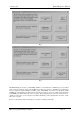
Using Windows Explorer, select the CD drive, and various files and folders will be displayed. One file will have
the name “setup”, or “setup.exe”. Using the mouse, move the cursor to this file, and “double-click” (ie click the
left button twice, rapidly) on it. This will start the installation program. This setup program allows you to
choose the folder in which you wish to install WinTekHelp, and to choose the default COMM Port. The default
folder is C:\WinTekHelp, and the default COMM port is COMM1. When you have selected the appropriate
drive, directory, and COMM Port, click on the button marked “Install”. The WinTekHelp software will self-
install, and return execution to Windows Explorer.
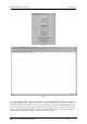
From within Windows Explorer, go to the folder on the disk drive that contains WinTekHelp. This is the folder
that you selected as part of the Installation Procedure. There you should see a file called either “WinTekHelp”
or WinTekHelp.exe”. Click on it once, so that it becomes highlighted. Then, with the left mouse button held
down, “drag” the item until you are over part of the Windows background, and release the mouse button. This
creates an Icon on your main windows screen which will be called “Shortcut to WinTekHelp”. From now on,
you can simply double-click on this Icon to start your WinTekHelp software.
2 Setting Up
First of all, install your exciter or receiver into its rack. If it is an exciter, ensure that it is connected to its Power
Amplifier.
Power up the exciter and power amplifier, or the receiver. Ensure that the Green power light is displayed on the
front panel.
You should connect the serial port of the exciter or receiver to the chosen COMM port of your PC, as described
in Section 1.
You may find that your exciter or receiver has a red flashing Alarm signal on the front panel. This is probably
indicating that the current channel has not yet been programmed.
Most personal computers use 9-pin, male, D connectors, for their COMM ports. RF Technology exciters and
receivers have a serial port on their front panels, with a 9-pin female D connector. Connect these two connectors
with a serial cable which has a female 9-pin D on one end and a male 9-pin D connector on the other. The cable
assembly should be a “straight through” type, ie with pin 2 connected to pin 2, pin 3 to pin 3, and pin 5 to pin 5.
RF Technology provide an optional serial cable, order part number TTC1-9, which can be used to connect your
PC to the receiver or exciter.