
User manual


The second stage, marked as “Reference Clocks”, may be required from time to time
depending on how accurate the user wants to keep the exciter’s transmit frequency. The
standard exciter comes with 12.0MHz crystals which have a 5ppm accuracy. These crystals
will age a few
ppm per year. One of these crystals is “locked” to the other with a software
based feedback network.
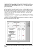
In order to calibrate the reference oscillators, the user will need to attach an external reference
to the exciter. If the external reference option has been chosen when ordering the exciter then
this can be achieved by connecting a reference clock to the ext. reference BNC connector in
the centre of the rear panel of the exciter. If that option has not been chosen, then the left side
cover will need to be removed and the external reference attached to J4. This can be found
slightly to the right of the
centre of the bottom edge of the assembly. The power supply
section is just to the left of J4.
The external reference must have a power level of at least +5dBm. It can be any multiple of
128kHz greater than 512kHz, or any multiple of 160kHz greater than 480kHz, or any multiple
of 500kHz. It should not exceed 10MHz.
The reference clock should be attached, and have been attached for at least 20 seconds before
the user selects the “Reference Clocks” button.
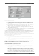
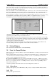
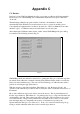
Fig. C.2 shows the graphical window that is displayed when the “Reference Clocks” button is
pushed.
The display shows the performance of the software based frequency tracking system.
Fig. C.2