
User manual


RF Technology WinTekHelp User Manual Page 32
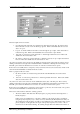
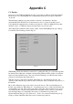
3.3.2 Parameter Programming for the Receiver WinTekHelp User Manual
The COS output can have four states:
1. Open Circuit: COS+ and COS- are isolated from ground and from each other. Dc current cannot
flow from COS+ to COS-, nor from either leg to ground. If this is the Default State, the asserted
state is “Looped”.
2. Looped: dc current will flow from COS+ to COS- through an opto-coupler. COS+ and COS- are
isolated from ground. If this is the Default State, the asserted state is “Open Circuit”.
3. 12V: COS- is connected to ground, and COS + to 12V through a 680 ohm resistor. If this is the
default state, the asserted state is “0V”.
4. 0V: COS- is connected to ground, and COS + is shunted to COS- by an opto-coupler that is turned
hard on. If this is the default state, the asserted state is “12V”.
Any of these four states can be selected to be the default (ie unasserted) state of the COS pair. This is done by
clicking on the button to the right of the “Default COS State” field that has a black upside down triangle on it.
This will open a menu from which the user can select one of the above-mentioned four options.
If the receiver successfully tunes to a frequency, it may assert COS. If it does, the asserted state of COS can be
derived from the Default State as indicated in the above table.
The Loop output can have two states:
1. 0V: Line+ and Line- are isolated from ground. If this is the Default State, the asserted state is
“Looped”.
2. 12V: Line- is connected to ground, Line+ to 12V through a 680-ohm resistor. If this is the default
state, the asserted state is “0V”.
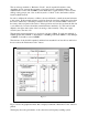
Any of these two states can be selected to be the default (unasserted) state of the Line pair. This is done by
clicking on the button to the right of the “Default Line State” field that has a black upside down triangle on it.
This will open a menu from which the user can select one of the above-mentioned two options.
If the receiver successfully tunes to a frequency, it may assert Loop. If it does, the asserted state of Loop can be
derived from the Default State as indicated in the above table.
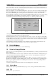
There are two timeout values defined for scanning operation.
• The first is entitled “Time that a Non Priority frequency is given preference after being left for a
Priority frequency”.
If the receiver successfully tunes to a frequency, which is not the priority frequency, it will keep
trying the priority frequency every so many seconds (as defined by the Priority Timeout value). If,
when testing the priority frequency, it is able to successfully tune to it, it will remain locked on to the
priority frequency. If, though, after a short period, the priority frequency loses carrier, or has too
much noise etc, it will resume scanning. Its scanning, though, will now be different from before, it
Fig. 19