
User manual


RF Technology WinTekHelp User Manual Page 31
WinTekHelp User Manual 3.3.2 Paramater Programming for the Receiver
The level, at which Low Battery Alarms are generated, can be defined in the box called, “Exciter Low Battery
Alarm level”.
The exciter will normally key up because PTT or LOOP, etc are asserted, and transmit forever. If the value in
the “Max Transmit Time” Box is non-zero, then the exciter will key off after the defined time, and generate a
Transmit Timeout Alarm. The time can be entered in hours, minutes, and seconds. For example, “3:21:30” is 3
hours, 21 minutes, and 30 seconds. One can enter seconds (eg 1000), and WinTekHelp will automatically
convert that to hours, minutes, and seconds. If one clicks at the top of the “Spin Button” to the right of the “Max
Transmit Time” field, the time will increment one minute. By clicking on the bottom of the “Spin Button”, the
time will decrease by 1 minute.
The middle section of the dialog box is devoted to Continuous Wave Identification (CWID). This is a method of
station Identification in which a string of Morse encoded characters are transmitted on the carrier. This string
can be transmitted periodically or just once, or never. If the Start Delay is negative then CWID is disabled. If
the Start Delay is greater than or equal to zero, then it will be transmitted periodically if the CWID period is non-
zero, or else just once when PTT or LOOP are asserted, if the CWID Period is zero. The message that is sent is
defined in the box CWID Message. The string of characters is sent at a nominal rate of 20wpm. The tone bursts
have an audio frequency of 1028Hz, and are transmitted at 30% of rated maximum deviation.
The right section of the dialog box devoted to the Power Amplifier.
The fields are:
1) Serial No: Each PA can have a unique serial number. It can help with equipment tracking if the
PA’s serial number is saved in the Flash memory of the exciter
2) Forward Power: The exciter monitors the forward power, keeping it locked at the level defined
here.
3) Reverse Power: This defines both the reverse power level that causes a reverse power alarm, and
the level of reverse power at which forward power is reduced. It is expressed as a percentage of the
peak forward power.
4) The Low Power Alarm: This is also expressed as a percentage of (2). It defines the power level
that causes a low power alarm.
5) If the battery voltage on the PA, falls below the Low Battery Level, a Low Battery Alarm is
generated
6) If the source pins of the output power FETs, in the PA, attempt to exceed the temperature defined
in the “Max Temperature” field, then the forward power will be reduced.
7) The Max Output and Max Preamp currents are the dc currents in these stages that, if exceeded, will
cause an Alarm (and the exciter will stop transmitting!).
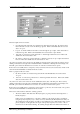
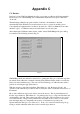
3.3.2 Parameter Programming for the Receiver
Figure 19 illustrates the dialog box used to present parameter data (and modify/create) parameter data for a
receiver.
To erase the existing parameter data on a receiver, one can click on the “Reset Parameters to their Defaults”
button.
The “Channel Select Override” parameter allows the user to override any channel (or slot) programming from
the rear panel. If this parameter is any value from 0 to 255, then the rear panel channel (or slot) selection is
ignored and this parameter value is used instead. This feature saves the need to manually set jumpers on the rear
panel.
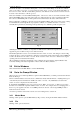
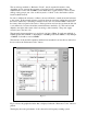
Note that the MODEL and SERIALNO parameters cannot be erased or overwritten. These can only be set in the
initial factory calibration.
The “Carrier Alarm Level” is the level of received signal, below which a Carrier Low Level Alarm is generated.
The parameters of Model, Serial No, and Battery Alarm level are as defined for the exciter (see 3.3.1)
The Fast Noise Threshold, is a level of signal, below which, short-term losses (< 150milliseconds) of signal, do
not cause the Squelch to Open.
The noise blanker of the receiver can be set to on or off, by the “Noise Blanker” field.